Remote-monitoring power free automatic compensating controller

A technology of remote monitoring and automatic compensation, applied in the direction of reactive power adjustment/elimination/compensation, reactive power compensation, etc., can solve the problems of inability to achieve reactive power compensation, low intelligence, short capacitor life, etc., to achieve easy standardization and Standardized management, high level of intelligence, and good capacity scalability

Inactive Publication Date: 2005-12-21
赵勤彪
View PDF0 Cites 5 Cited by
  • Summary
  • Abstract
  • Description
  • Claims
  • Application Information

AI Technical Summary

Problems solved by technology

[0002] At present, in the known reactive power (power factor) compensation controller, a control circuit is connected to a set of low-voltage power compensation capacitors with fixed specifications. This kind of compensation controller switches according to the power factor. , the following situation may occur: after putting in several sets of capacitors, the power factor is a little lower than the preset value, and after putting in another set of capacitors, the power factor is overcompensated. If a smaller compensation capacitor is used, the power consumption peak Sometimes even if all of them are put in, the compensation may not be enough, and it is impossible to achieve good reactive power compensation.
And the on-site voltage data can only be sampled one way or without sampling. When the voltage is too high, the capacitor cannot be cut off, and the loss under the overvoltage of the capacitor cannot be protected; the known reactive power compensator cannot automatically cool down at high temperatures; The power compensator can only be used as a separate device, and it cannot realize remote viewing of data and operating conditions. It has the disadvantages of low intelligence, inability to realize remote monitoring, poor flexibility, poor reliability, short capacitor life and poor capacitor scalability.

Method used


Image

  • Remote-monitoring power free automatic compensating controller
  • Remote-monitoring power free automatic compensating controller
  • Remote-monitoring power free automatic compensating controller

Examples


Embodiment Construction

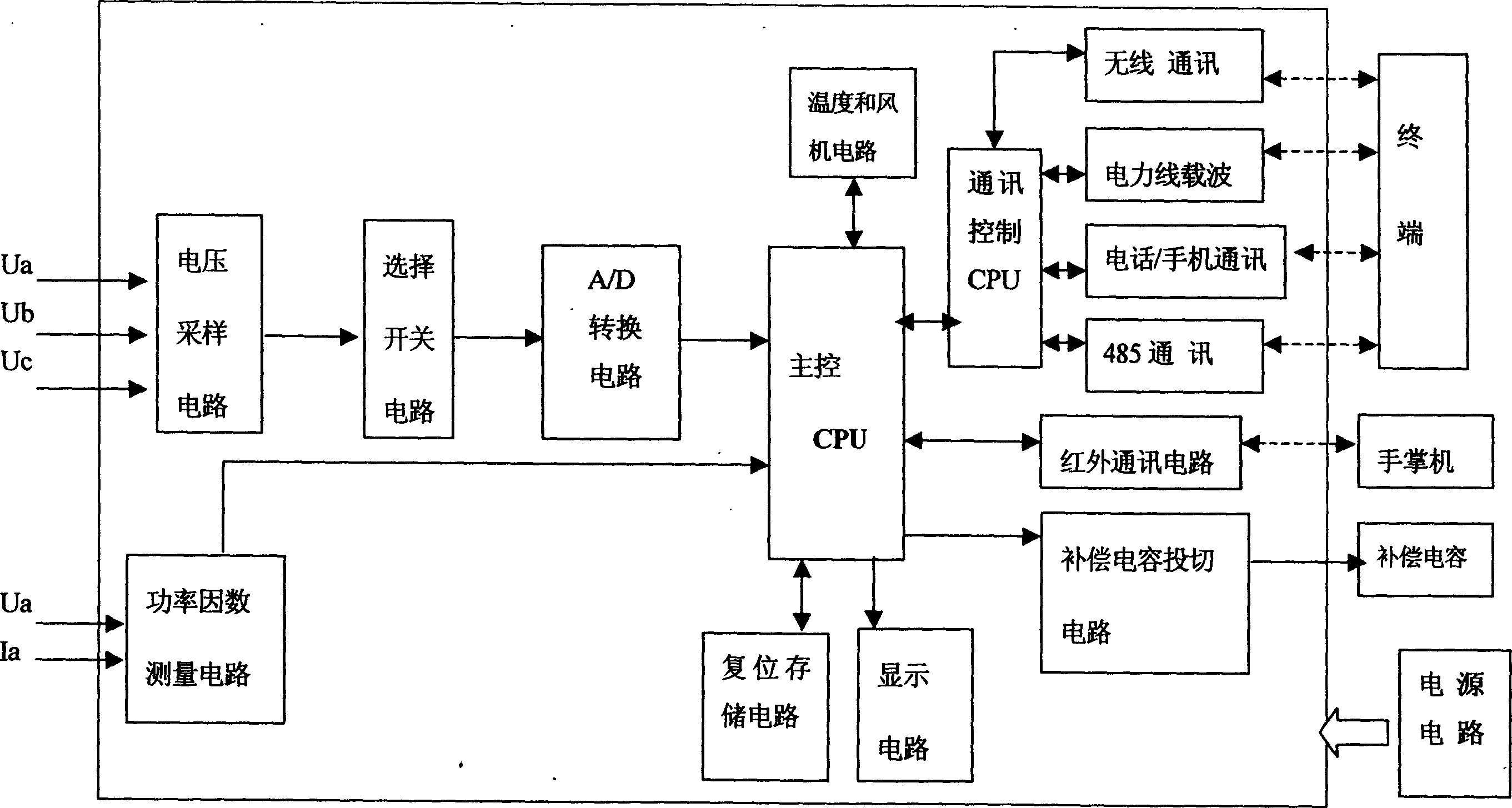
[0012] exist figure 1 Among them, the present invention includes a power supply circuit, a voltage sampling circuit, a selection switch circuit, an A / D conversion circuit and a main control CPU connected in sequence, and a reset storage circuit and a display circuit are connected to the main control CPU, and the main control CPU They are respectively connected with the power factor measurement circuit, the compensation capacitor switching circuit, the infrared communication circuit and the communication control CPU, and the communication control CPU is connected with the signal transceiver.

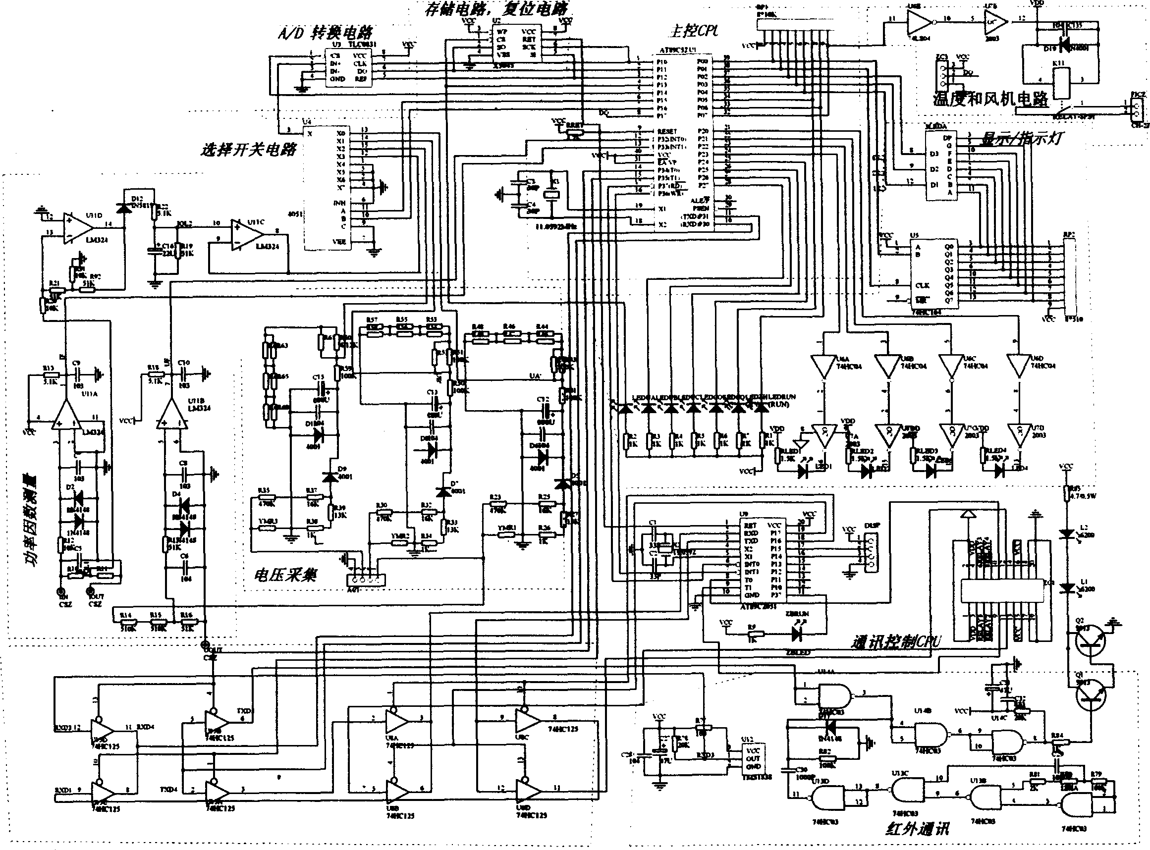
[0013] exist figure 2 , in, the main control CPU of the present invention is made of integrated circuit U1 and its peripheral circuit, and the model that integrated circuit U1 selects is AT89C52, and its pin 6, pin 7 are connected with selection switch circuit, and selection switch circuit is made of integrated circuit U4 , the model is 4051; the pin 1, pin 2, pin 3, and pin 4 of the in...


PUM


Abstract

The compensating device includes power supply circuit and cascaded voltage sampling circuit, selective switch circuit, A / D conversion circuit and main control CPU. Reset storage circuit and display circuit are connected to the main control CPU. Characters are that the main control CPU is connected to power factor measurement circuit, circuit for switching compensation capacitances, infrared communication circuit, and communication control CPU. The said communication control CPU is connected to transmitter receiver set of signal. Advantages are simple structure, reasonable design, high intelligence, reliable quality, good maintainability and easy of standardization etc.

Description

technical field [0001] The invention relates to a remote monitoring low-voltage power reactive power compensation device in the technical field of power supply. Background technique [0002] At present, in the known reactive power (power factor) compensation controller, a control circuit is connected to a set of low-voltage power compensation capacitors with fixed specifications. This kind of compensation controller switches according to the power factor. , the following situation may occur: after putting in several sets of capacitors, the power factor is a little lower than the preset value, and after putting in another set of capacitors, the power factor is overcompensated. If a smaller compensation capacitor is used, the power consumption peak Sometimes even if all of them are cast, the compensation may not be enough, and good reactive power compensation cannot be achieved. And the on-site voltage data can only be sampled one way or without sampling. When the voltage is ...

Claims


Application Information

Patent Timeline
Patent Type & Authority Applications(China)
IPC IPC(8): H02J3/18
CPCY02E40/30
Inventor 郑结明胡国攀王庆山
Owner 赵勤彪
Why Eureka
Try Eureka