
Digital phase-frequency identification circuit

A technology of phase frequency and circuit identification, which is applied to circuits and electrical components that oscillate independently of each other, and can solve problems such as excessive jitter.

Inactive Publication Date: 2005-12-21
AMICCOM ELECTRONICS CORP
View PDF2 Cites 3 Cited by
  • Summary
  • Abstract
  • Description
  • Claims
  • Application Information

AI Technical Summary

Problems solved by technology

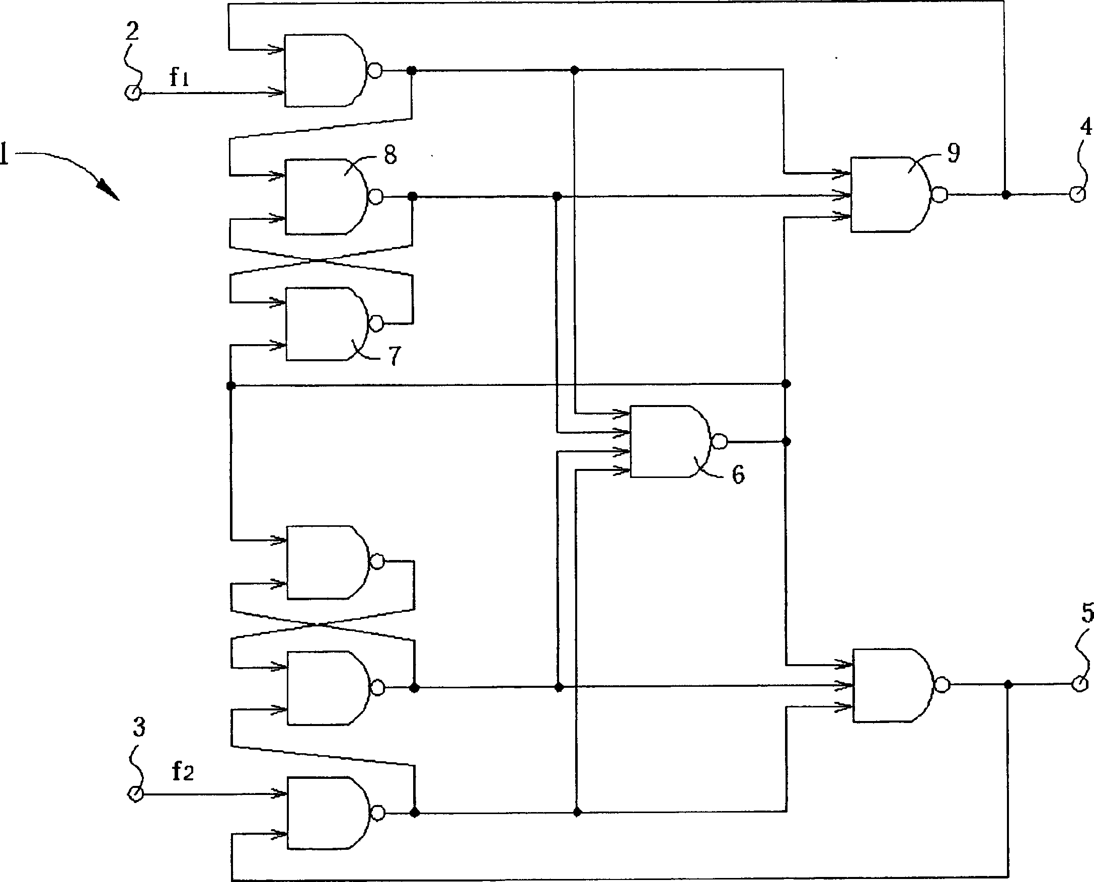
Although DPFD11 can indeed solve the above-mentioned problem of excessive jitter, it is obvious that compared with the nine logic gates contained in DPFD 10, the as many as eleven logic gates contained in DPFD 11 are obviously too large. too much

Method used


Image

  • Digital phase-frequency identification circuit
  • Digital phase-frequency identification circuit
  • Digital phase-frequency identification circuit

Examples


Embodiment Construction

[0053] see Figure 5 , Figure 5 It is a circuit diagram of a DPFD 50 in the preferred embodiment of the present invention. DPFD 50 comprises a first SR latch 52, a second SR latch 54, a third SR latch 56 and a fourth SR latch 58, the first and the SR latches 52 and 54 Each includes a pair of interleaved NOR gates, and the third and third SR latches 56 and 58 respectively include a pair of interleaved NAND gates (NAND gates), and each NOR gate or NAND gate includes Two input terminals.

[0054] The first SR latch 52 comprises a first NOR gate 60 and a second NOR gate 62, an input terminal of the first NOR gate 60 is used as the S input terminal of the first SR latch 52, and the second OR One input end of the NOT gate 62 is used as the R input end of the first SR latch 52, and the other input end of the first NOR gate 60 is connected to the output end of the second NOR gate 62 in an interleaved manner, and the second NOR gate 62 The other input end of the NOR gate is connec...


PUM


Abstract

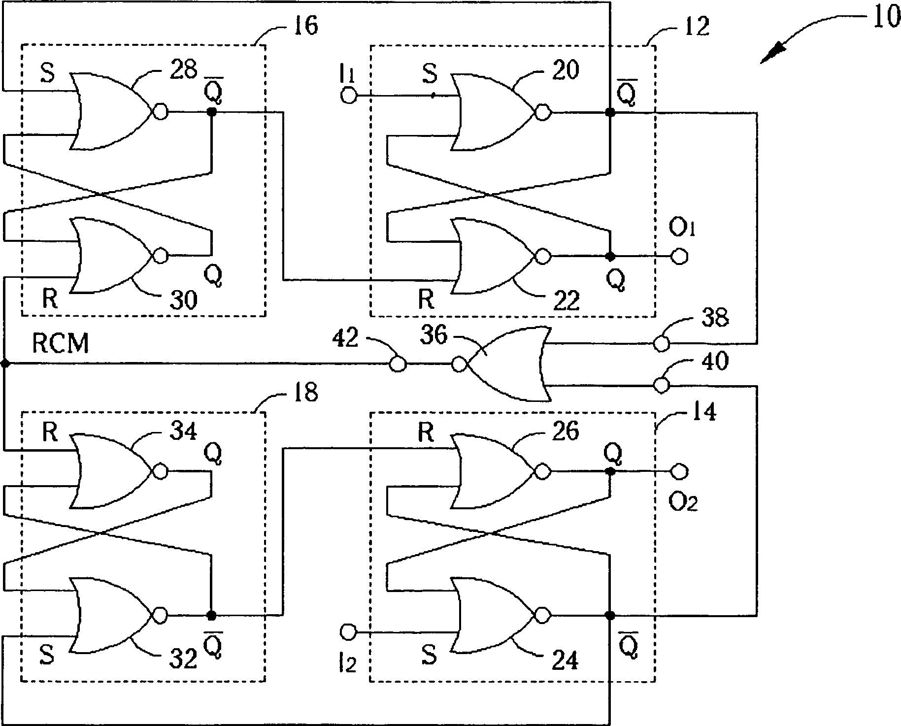
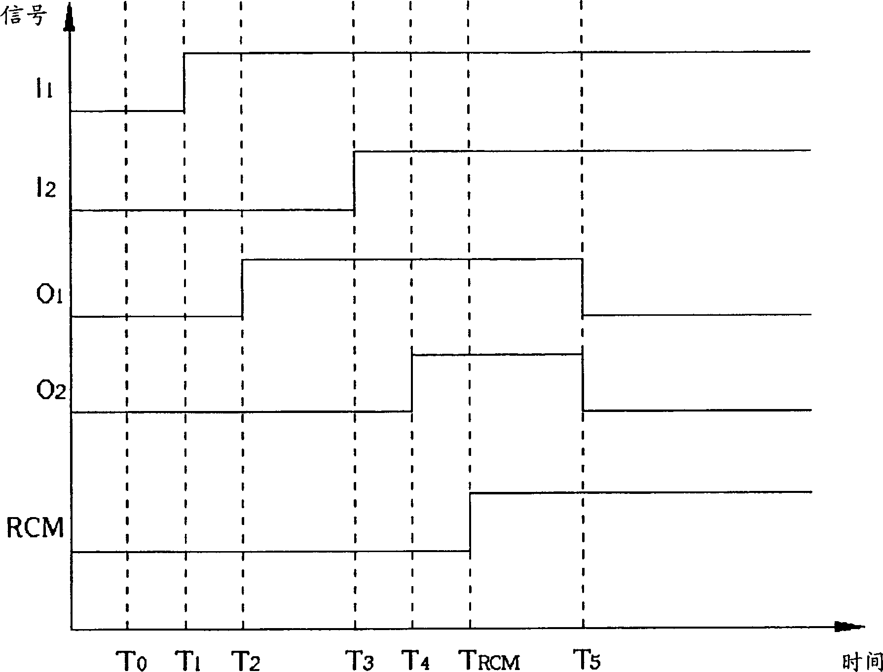
The discrimination circuit includes following parts: a first SR latch in use for generating a first output signal at predetermined state setup; a second SR latch in use for generating a second output signal at predetermined state setup; a predetermined state testing circuit in use for detecting the first output signal and the second output signal, and outputting a RCM signal based on the detection; a first predetermined state control circuit in use for setting up the first SR latch at the predetermined state based on the RCM signal; a second predetermined state control circuit in use for setting up the second SR latch at the predetermined state based on the RCM signal. The first SR latch and the first predetermined state control circuit can receive a first input signal. The second SR latch and the second predetermined state control circuit can receive a second input signal.

Description

technical field [0001] The invention provides a digital phase identification circuit, in particular a digital phase frequency identification circuit with simple structure. Background technique [0002] Generally speaking, a digital phase-frequency discriminator (DPFD) can provide an output signal according to the phase or frequency relationship between two input signals. For example, in a phase-locked loop, a digital phase-frequency discrimination circuit can be used to compare a reference signal with a signal output from a voltage-controlled oscillator (VCO) to detect The phase difference or frequency difference between the two signals is obtained, and an output signal related to the phase difference or the frequency difference is provided accordingly, and the frequency of the voltage-controlled oscillator can vary with the output signal Change. In this way, the signal output from the voltage controlled oscillator can gradually be in phase or in the same frequency as the ...

Claims


Application Information

Patent Timeline
IPC IPC(8): H03D13/00
Inventor 张德智
Owner AMICCOM ELECTRONICS CORP
Learn More