
Network system based on layer structure and node positioning method therefor

A technology of network system and positioning method, applied in the field of positioning of network system and its nodes, to achieve uniform and reasonable load and improve system communication efficiency

Inactive Publication Date: 2005-12-21
何韶军 +6
View PDF0 Cites 12 Cited by
  • Summary
  • Abstract
  • Description
  • Claims
  • Application Information

AI Technical Summary

Problems solved by technology

In this case, when an enterprise network consists of multiple remote subnets, and users want to access or perform operations on remote subnets in different places, the above common network positioning methods will not be able to meet the needs of users. This requires an effective positioning method to solve this problem

Method used


Image

  • Network system based on layer structure and node positioning method therefor
  • Network system based on layer structure and node positioning method therefor
  • Network system based on layer structure and node positioning method therefor

Examples


Embodiment Construction

[0048] The present invention will be described in detail below in conjunction with the accompanying drawings and specific embodiments.

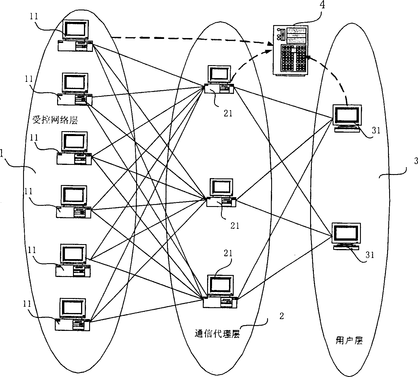
[0049] see figure 1 , is a schematic structural diagram of the network system of the present invention, the network system includes: a controlled network layer 1, a communication agent layer 2, an application layer 3 and a positioning center 4; wherein, the controlled network layer 1 includes one or more than one terminal node 11, the terminal node 11 can provide various specific services to the user; the communication proxy layer 2 includes one or more transparent proxy nodes 21; the application layer 3 includes one or more control nodes 31, so The control node 31 is used to provide an interactive interface for user access and control, and the transparent proxy node 21 is a transfer station for communication between the terminal node and the control node. The connections between nodes at different levels are in a many-to-many network struct...


PUM


Abstract

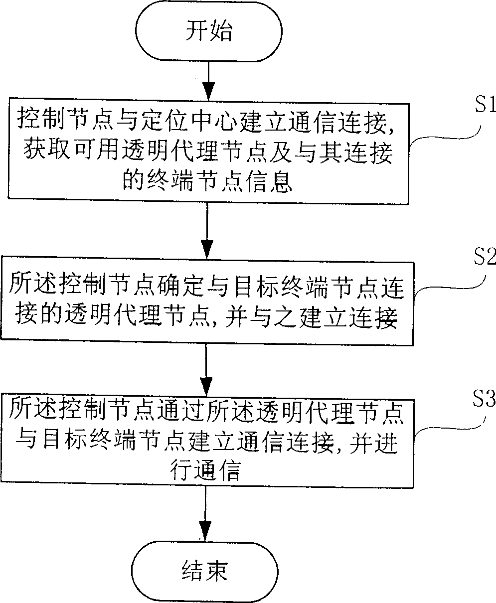
The method includes steps: building communication connection between the control node and the center of location; inquiring about list of transparent proxy node maintained by the center of location; obtaining position information of available transparent proxy nodes, and information of terminal nodes connected to transparent proxy nodes; the said position information is as IP address and port number of node; based on IP address and port number of target terminal node, the said control node determines a transparent proxy node connected to the target terminal node, and builds link to the proxy node; through the said transparent proxy node, the control node builds connection with the target terminal node, and carries out communication with it. The invention reduces need of IPv4 address of Internet by corporate network. Thus, under protection of firewall, each sub net of corporate network can access each other without need of opening additional port so as to raise security.

Description

technical field [0001] The invention relates to a system and method in the field of network application technology, in particular to a layered structure-based network system and a node positioning method thereof. Background technique [0002] Accurately locating the target node is the first problem to be solved before each node in the network system communicates. From the emergence of the Internet to the current extreme expansion, the positioning method of network system nodes is constantly evolving to adapt to the development of the Internet. From the simple node positioning method using IP address and general port number at the beginning, to the current node positioning method suitable for various special network requirements, it can be found that the positioning methods are all changed to adapt to the changing needs of the Internet . [0003] As we all know, the current Internet public network IPv4 addresses are very scarce, especially in countries and regions that ente...

Claims


Application Information

Patent Timeline
Patent Type & Authority Applications(China)
IPC IPC(8): H04L29/12
Inventor 何韶军郭世泽李基牛伟段榕张永苏享茂
Owner 何韶军
Learn More