
Ultrasonic motor

An ultrasonic motor, ultrasonic technology, applied in the directions of generators/motors, electrical components, piezoelectric effect/electrostrictive or magnetostrictive motors, etc., can solve the limitation of the layout position, difficult to ensure the holding torque, difficult to improve the stop position Resolution and other issues, to achieve the effect of less layout space and improved efficiency

Inactive Publication Date: 2005-12-28
OLYMPUS CORP
View PDF0 Cites 4 Cited by
  • Summary
  • Abstract
  • Description
  • Claims
  • Application Information

AI Technical Summary

Problems solved by technology

[0007] However, the linear ultrasonic motors disclosed in Patent Documents 1 and 2 have problems in that it is difficult to ensure holding torque and improve the resolution of the stop position compared with the ring-shaped ultrasonic motors.
[0008] On the other hand, although the ultrasonic motor disclosed in Patent Document 3 is a rotary type, it must have a central axis passing through the central part. For example, it is difficult to apply to a device that requires a large space in the central part such as a lens barrel. middle
In addition, since the frame that fixes the vibrator itself acts as a biasing spring, the above-mentioned frame has a rigidity problem, and it is difficult to stably fix the rotor and the vibrator.
In addition, in order to suppress the friction loss caused by the force pressing the vibrator, it is necessary to arrange a plurality of vibrators facing each other outside the rotor, and the arrangement position of the vibrator is limited. In addition, the electrical wiring is also complicated.

Method used


Image

  • Ultrasonic motor
  • Ultrasonic motor
  • Ultrasonic motor

Examples


Embodiment Construction

[0039] Embodiments of the present invention will be described below with reference to the drawings.

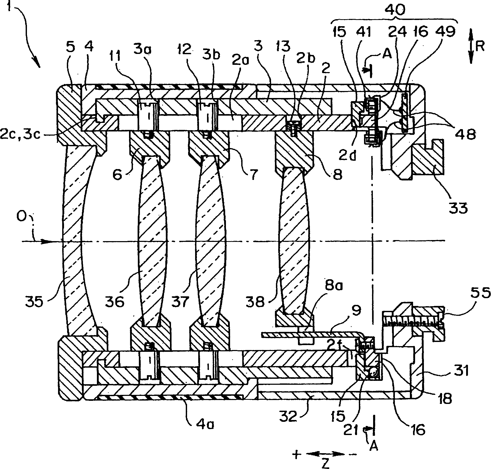
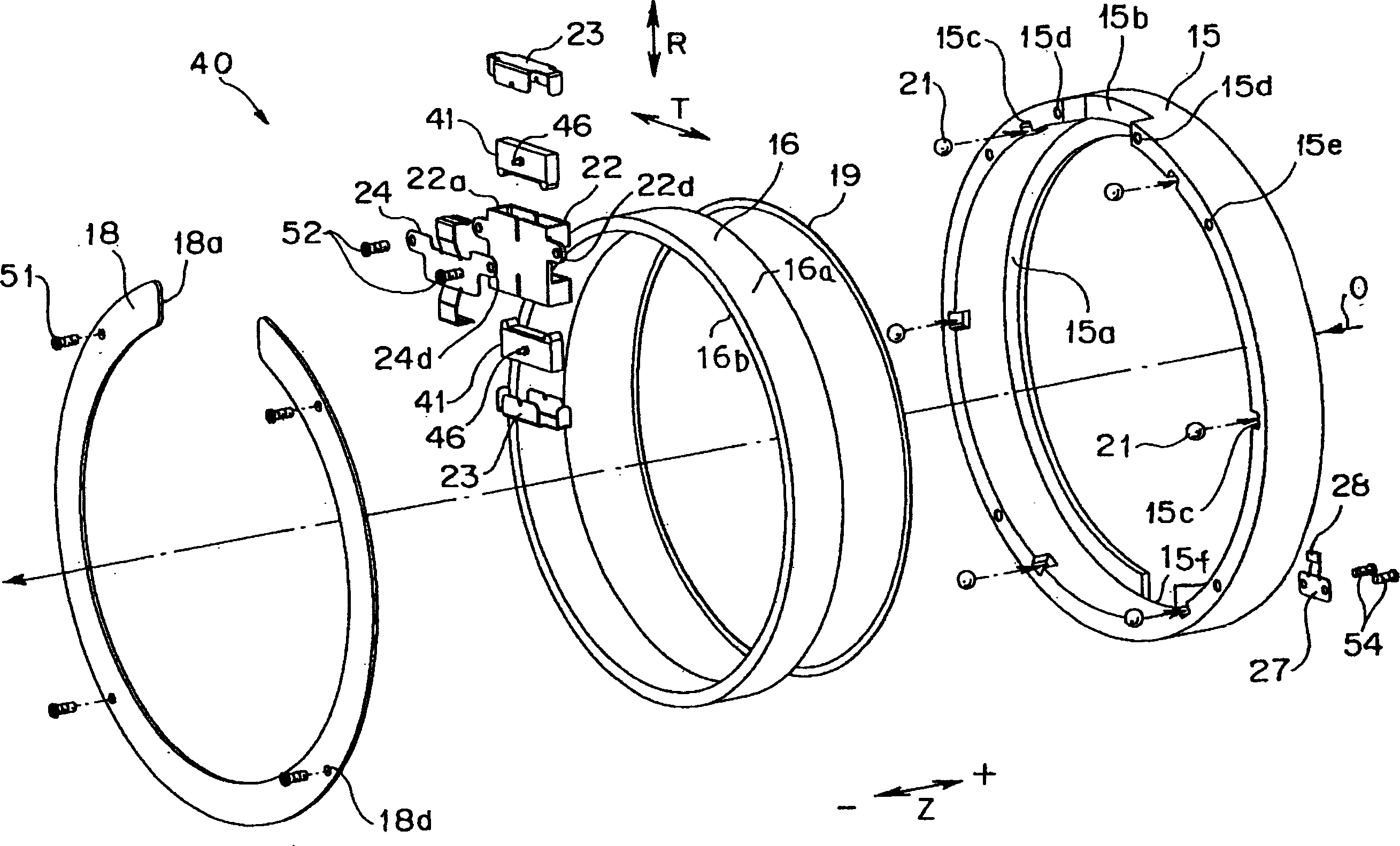
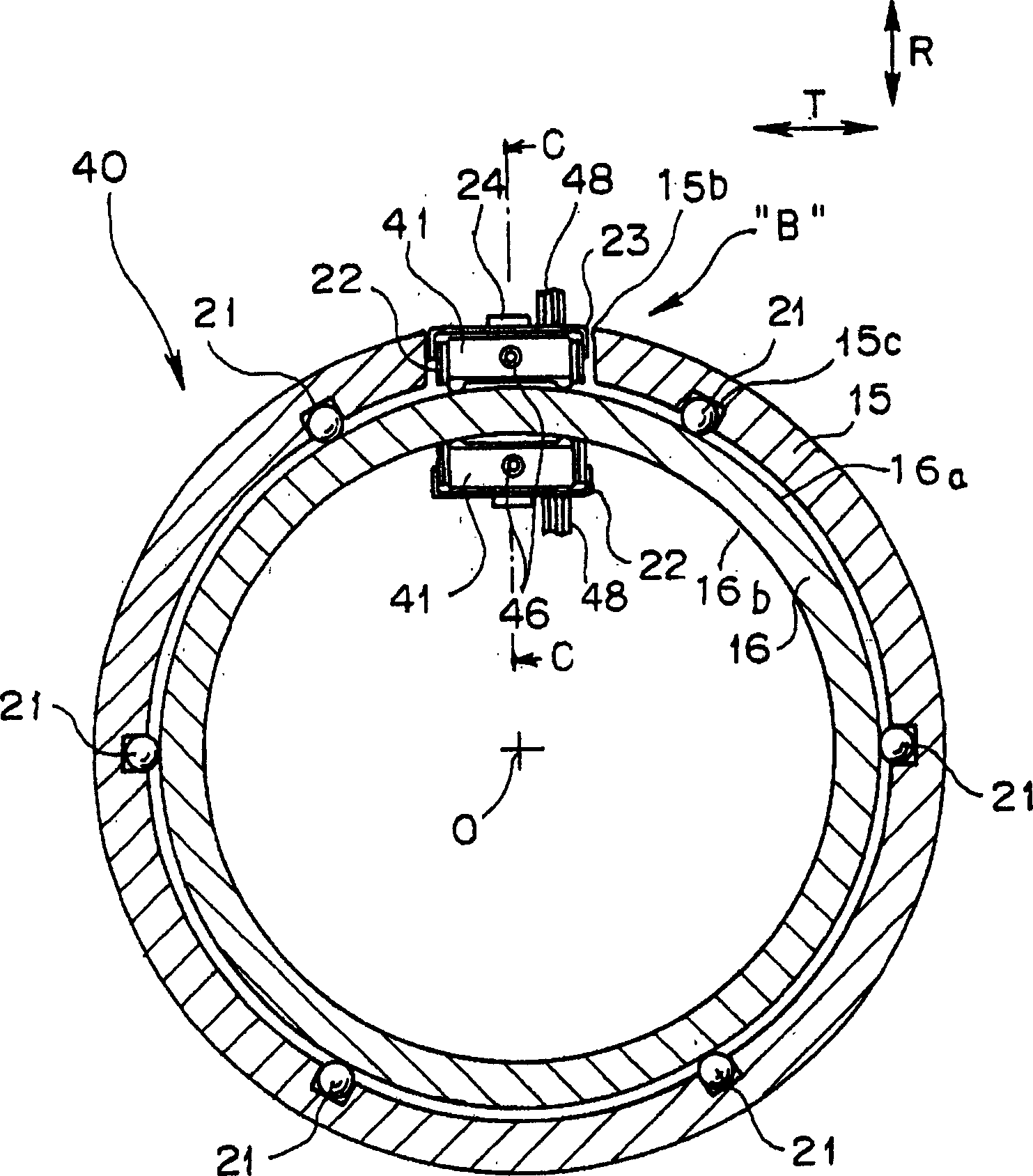
[0040] figure 1 It is a vertical sectional view of the optical axis of the lens barrel including the ultrasonic motor according to the first embodiment of the present invention; figure 2 It is an exploded perspective view of the above-mentioned ultrasonic motor, but it is a perspective view seen from the imaging side in the direction of the optical axis; image 3 is alongfigure 1 The cross-sectional view of line A-A in ; Figure 4 yes image 3 The enlarged view of part B of , showing the installation state of the vibrator of the above-mentioned ultrasonic motor part; Figure 5 It is a perspective view of a vibrator assembly in a state where the above-mentioned vibrator is assembled in a vibrator holder; Image 6 is an exploded perspective view of the vibrator assembly; Figure 7 yes image 3 The enlarged cross-sectional view of part C-C in , showing the installation sta...


PUM


Abstract

An ultrasonic motor which has a ring structure, improves the efficiency of the motor, and has less restriction on the layout space. The ultrasonic motor (40) of the present invention is used as the driving source of the lens barrel after being assembled, and has: a stator (15); an annular rotor (16); a pair of vibrators (41); a vibrator holder (22) supporting the vibrator; The vibrator pressure plate (23) supporting the support shaft (46) of the vibrator; the compression spring (24), exerts force on the vibrator to the rotor side through the vibrator pressure plate, so that it can slide freely; the ball (21) can be embedded in the stator in a rolling manner In the fitting part with the rotor. A pair of vibrators are installed in the concave portion (15b) of the stator through a vibrator holder or the like, and the driver (44) of the vibrator clamps the rotor while always pressing the outer and inner circumferential surfaces of the rotor. When the vibrator is excited and the driving part vibrates in an ellipse, it drives the rotor to rotate.

Description

technical field [0001] The present invention relates to an ultrasonic motor using a vibrator that excites an ultrasonic elliptical motion. Background technique [0002] Conventionally, Patent Document 1 or Patent Document 2 discloses a mounting structure of an ultrasonic motor that relatively moves a vibrator and a driven body, and the vibrator generates vibration formed by combining bending standing wave vibration and longitudinal vibration. Ultrasonic elliptical vibrations, the driven body comes into contact with the vibrator and applies force thereto. This ultrasonic motor is a linear drive type ultrasonic motor. [0003] Furthermore, the ultrasonic motor disclosed in Patent Document 3 is a rotary ultrasonic motor using a vibrator that generates ultrasonic elliptical vibrations, and is a motor using a rotor having a rotating shaft passing through the center. [0004] [Patent Document 1] Patent Publication No. 2871768. [0005] [Patent Document 2] Patent Publication No....

Claims


Application Information

Patent Timeline
IPC IPC(8): G02B7/04H02N2/00
Inventor 岸政典
Owner OLYMPUS CORP
Learn More