

Alarm data process and its processor in network system
A network system and data technology, applied in the field of network communication, can solve problems such as failure to eliminate faults in time, reduce fault handling efficiency, etc., achieve the effect of reducing heavy pressure and ensuring normal operation
- Summary
- Abstract
- Description
- Claims
- Application Information
AI Technical Summary
Problems solved by technology
Method used
Image

Examples
no. 1 example
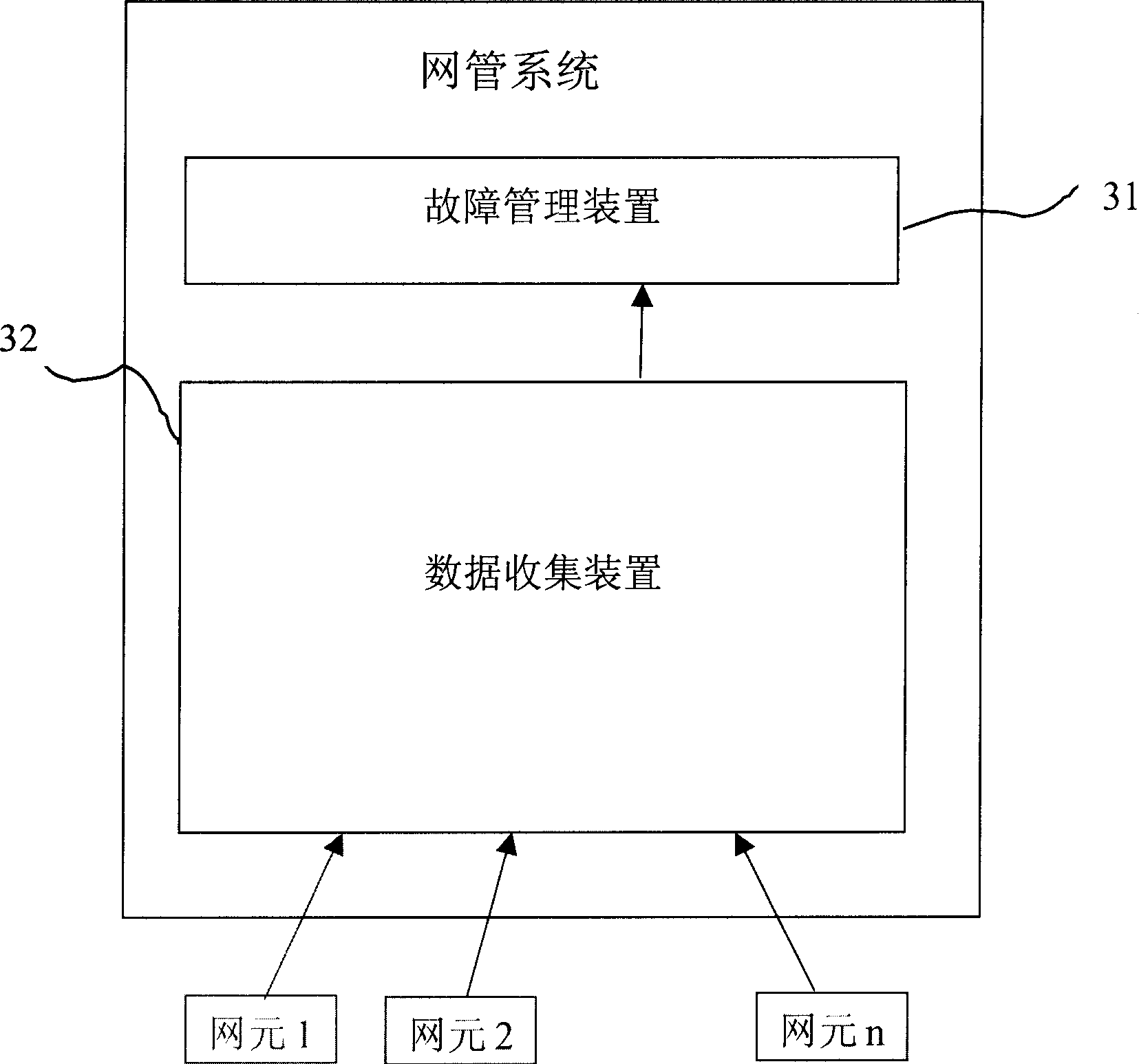
[0087] image 3 It is the block diagram of the first embodiment of the device of the present invention:
[0088] Among them, the fault management device 31 is used to perform centralized fault management on network element equipment, that is to say, to manage alarm data; the data collection device 32 is coupled to the fault management device 31, and is used to forward the alarm data of different network element equipment to the fault management device 31 .
[0089] Each network element device actively reports its alarm data to the data collection device 32 , of course, the data collection device 32 may obtain its alarm data in a certain way, for example, regularly polling the network element device.
no. 2 example
[0090] Figure 4 It is the block diagram of the second embodiment of the device of the present invention:
[0091] As shown in the figure, according to the second embodiment of the present invention, corresponding data parsing means are provided for alarm data of different types of network element equipment, for converting different types of alarm data into predetermined formats. In this embodiment, the device of the present invention comprises:
[0092] The data collection interface 321 is used to collect alarm data of different network element devices. Each network element device actively reports its alarm data to the data collection interface 321, and of course the data collection interface 321 can query the network element device to obtain its alarm data;
[0093] Multiple data analysis devices, coupled to the data collection interface 321, correspond to different types of network element equipment, and are used to convert the alarm data of the network element equipment ...
PUM
 Abstract
Description
Claims
Application Information