Imaging apparatus
一种摄像装置、摄像元件的技术,应用在图像通信、电视、彩色电视的零部件等方向,能够解决处理时间减半等问题,达到高画质的效果
- Summary
- Abstract
- Description
- Claims
- Application Information
AI Technical Summary
Problems solved by technology
Method used
Image
Examples
Embodiment 1
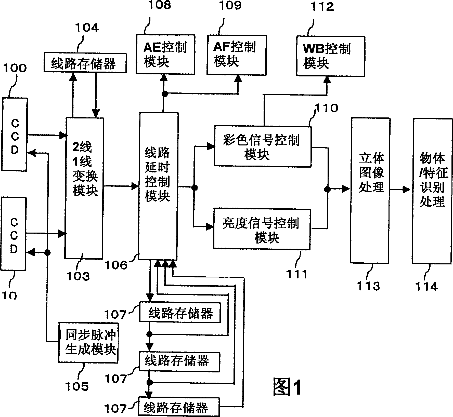
[0024] FIG. 1 is a block diagram showing an imaging device according to a first embodiment of the present invention.
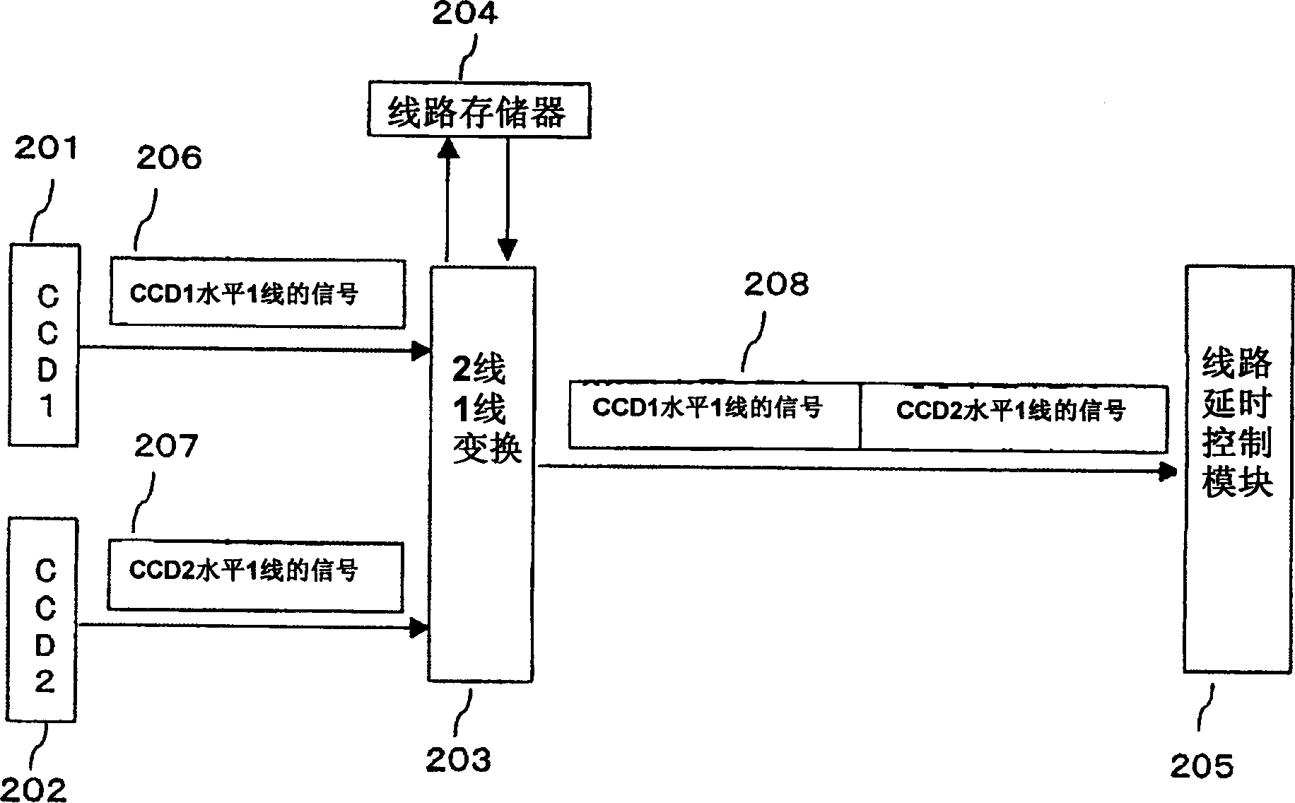
[0025] The first imaging device (hereinafter referred to as CCD) 101 and the second CCD 102 driven by the synchronization pulse generation module 105 output the subject image as an image signal, and the output 2 The signals are synthesized and transformed into one signal. Furthermore, after the converted signal is aggregated into signals of several lines by the line delay control module 106 and the line memory 107, the signals are processed by the exposure control module (hereinafter referred to as the AE control section), the focus control module (hereinafter referred to as the AF control module) The control unit) respectively performs exposure control and automatic focus control. In addition, in the white balance control module (hereinafter referred to as the WB control module), the white balance control is performed with the signal processed by the color s...
Embodiment 2
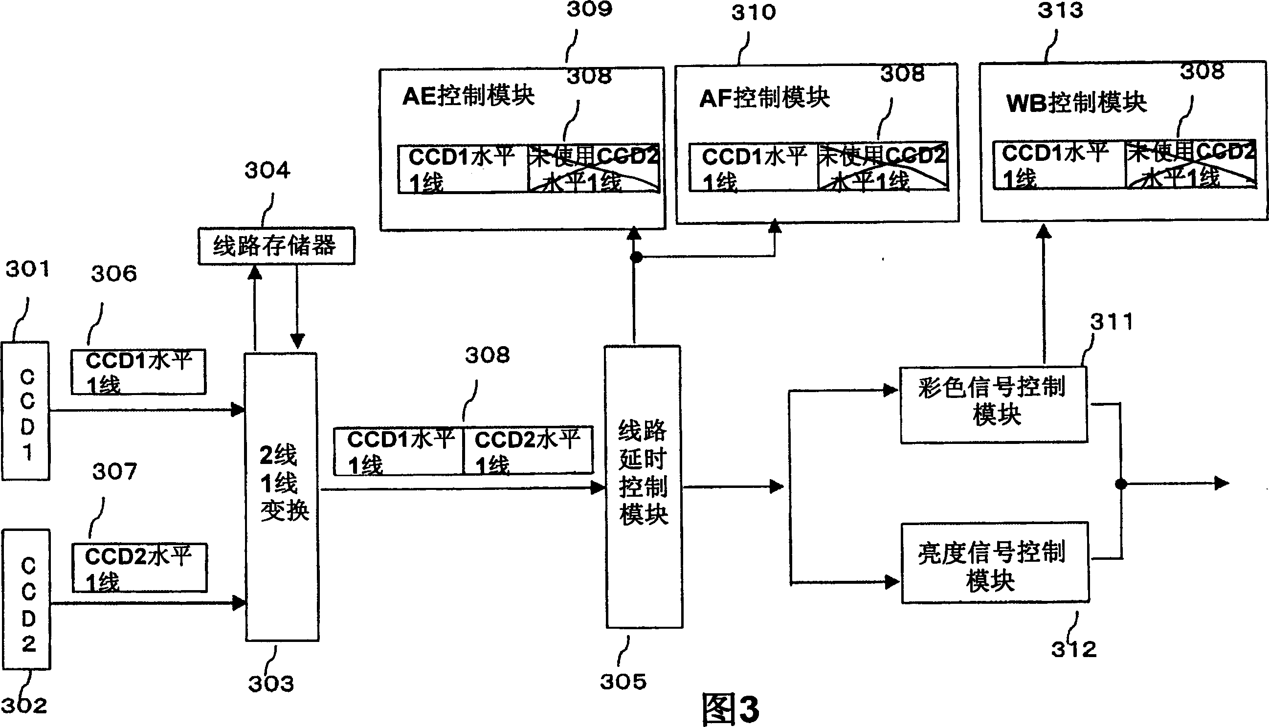
[0030] As a second embodiment, FIG. 3 shows that the signal from the first CCD and the signal from the second CCD are combined and converted into one signal, and AE control and AF control are performed using the signal from either the first or second CCD. , The signal flow chart of WB control.
[0031] 308 is a signal converted into one signal obtained by synthesizing two signals output from two CCDs for each horizontal one line by a two-line one-line conversion module. 309 is an AE control module for performing AE control using only one of the CCD signals converted into one signal synthesized for each of the above-mentioned horizontal 1 lines. 310 is an AF control module for performing AF control using only one CCD signal of one signal converted from the synthesis of each of the above-mentioned one horizontal lines. 313 is a WB control module for performing WB control using only one of the CCD signals converted into one signal synthesized for each of the above-mentioned hori...
Embodiment 3
[0034] As a third embodiment, FIG. 4 shows that AE control, AF control, and WB control are performed using the average of two CCD signals included in one signal converted from a signal obtained by combining the signal from the first CCD and the signal from the second CCD. signal flow chart.
[0035] 408 is a 2-line 1-line conversion module that converts 2 signals output from 2 CCDs to each horizontal 1-line and then converts it into one signal. 409 is an AE control module that performs AE control by using one signal converted from the synthesis of the above-mentioned two horizontal 1-wires. 410 is an AF control module that performs AF control by using a signal converted from the synthesis of each horizontal line. 413 is a WB control module for WB control using a signal converted from the synthesis of each of the above-mentioned horizontal 1 lines.
[0036] the above, and the first embodiment's figure 2 Similarly, the signal converted into one signal by the 2-wire-1-wire con...
PUM
 Abstract
Description
Claims
Application Information
 - R&D
- Intellectual Property
- Life Sciences
- Materials
- Tech Scout
- Unparalleled Data Quality
- Higher Quality Content
- 60% Fewer Hallucinations
Browse by: Latest US Patents, China's latest patents, Technical Efficacy Thesaurus, Application Domain, Technology Topic, Popular Technical Reports.
© 2025 PatSnap. All rights reserved.Legal|Privacy policy|Modern Slavery Act Transparency Statement|Sitemap|About US| Contact US: help@patsnap.com


