Multi output dc/dc converter for liquid crystal display device

A technology of liquid crystal display and converter, which is applied in the direction of output power conversion device, static indicator, and conversion equipment without intermediate conversion to AC, which can solve problems such as energy loss

Inactive Publication Date: 2005-12-28
KONINKLIJKE PHILIPS ELECTRONICS NV
View PDF1 Cites 8 Cited by
  • Summary
  • Abstract
  • Description
  • Claims
  • Application Information

AI Technical Summary

Problems solved by technology

Although this known system produces a well-defined LCD drive voltage, the application of such drive elements in combination with the load currents present in these amplifiers leads to a loss of energy in these amplifiers, especially in operational amplifiers, which Usually not accepted in practice

Method used


Image

  • Multi output dc/dc converter for liquid crystal display device
  • Multi output dc/dc converter for liquid crystal display device
  • Multi output dc/dc converter for liquid crystal display device

Examples


Embodiment Construction

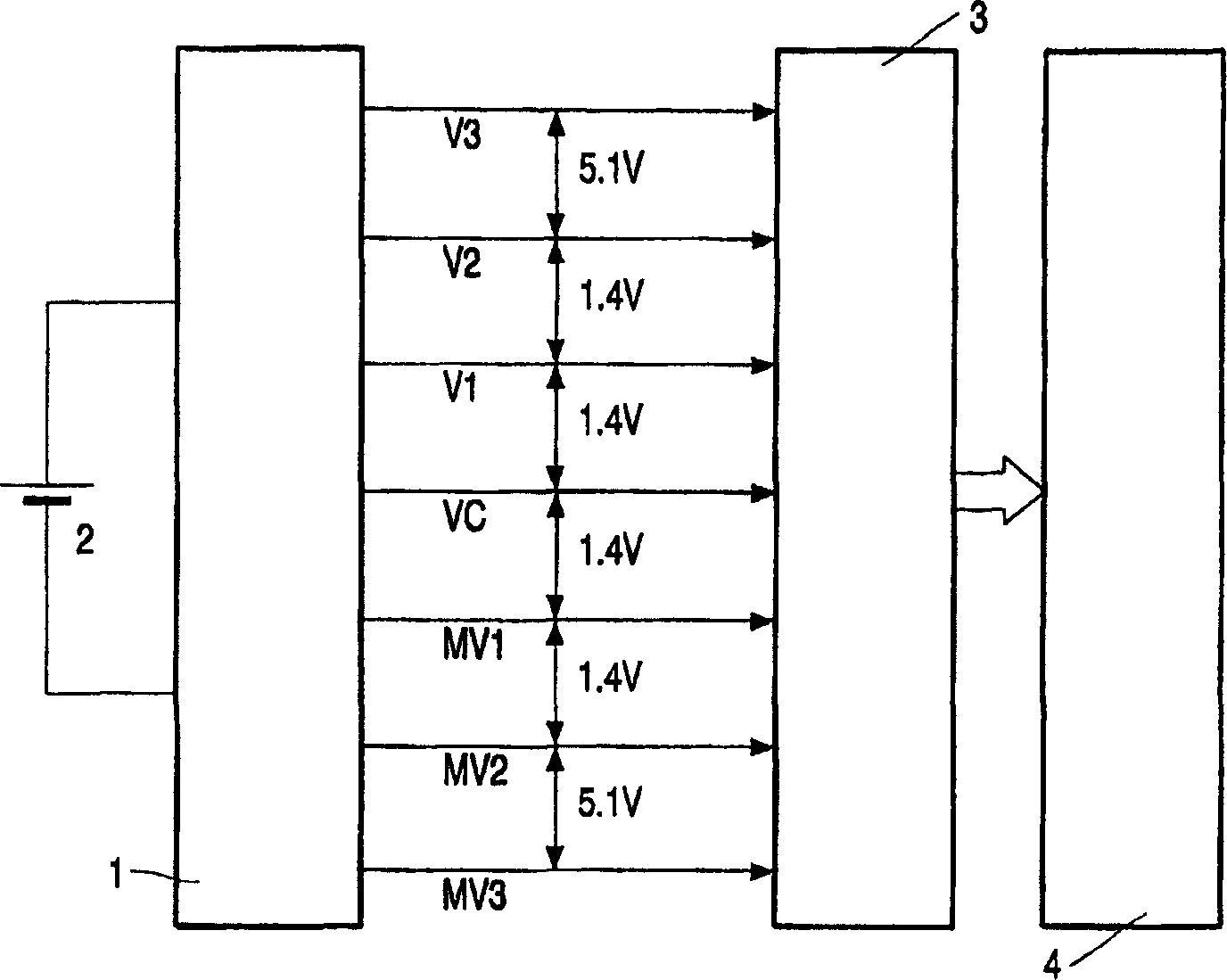
[0019] figure 1 is a schematic diagram of an LCD system with means for generating multiple symmetrical LCD voltages in the form of an LCD supply voltage generator 1 powered by a battery 2 and an LCD driver circuit 3 supplying LCD drive voltage to terminals of an LCD panel 4 . The LCD driver circuit 3 comprises matrix switching and control means in known manner. A matrix of 68 rows by 98 columns, or 3x98 columns for a color panel, is a practical structure for a cellular phone. The LCD system further includes a processor with a control algorithm to control the above hardware; this processor is not shown in the figure.

[0020] As an example, the matrix switch and control device may require the following LCD drive voltages: V3 = 15.8V; V2 = 10.7V; V1 = 9.3V; VC = 7.9V; MV1 = 6.5V; MV2 = 5.1V; and MV3 = 0V . These values ​​are shown in figure 1 middle. From these values ​​it can be seen that the 4 groups are represented by VC (V 公共 ) as the center of the 1.4V voltage extends...


PUM


Abstract

A liquid crystal display (LCD) system comprising means for generating a plurality of LCD driving voltages, the driving voltage values ​​being symmetrical about a predetermined voltage value, said means having a buffer capacitor structure providing a buffer capacitance for each LCD driving voltage, The LCD system further includes an LCD driver circuit having matrix switching and control means for supplying voltages corresponding to said LCD driving voltages to the terminals of the LCD panel resulting in appropriate brightness levels for the pixels of the LCD panel. In order to define the LCD drive voltage value, at least one charge pump unit is provided with at least one pump capacitor and a switching element, wherein at least one charge pump unit is connected to a buffer capacitor.

Description

technical field [0001] The present invention relates to liquid crystal display (LCD) system, it comprises the device that produces a plurality of LCD drive voltages, and this voltage value is symmetrical about predetermined voltage value, and above-mentioned device has buffer capacitor structure and provides buffer capacitance for each LCD drive voltage, LCD system further An LCD driver circuit with matrix switches and control means is included to supply the LCD panel terminals with voltages corresponding to the aforementioned LCD drive voltages resulting in appropriate brightness levels for the pixels of the LCD panel. Background technique [0002] What is actually required is an LCD module which is powered only by a given voltage source, especially a battery, or a voltage derived from a battery and which has a given form for the picture on the panel. One of the most important applications for small LCD systems is the application in cellular phones; the battery is the volta...

Claims


Application Information

Patent Timeline
Patent Type & Authority Applications(China)
IPC IPC(8): G09G3/36H02M3/07
CPCG09G3/3696G09G2310/0275H02M3/07H02M1/009G02F1/133
Inventor F·A·C·M·斯库夫斯W·J·R·范利尔
Owner KONINKLIJKE PHILIPS ELECTRONICS NV
Why Eureka
Try Eureka