Shock-proof energy conversion controller

A control device and energy conversion device technology, applied in the direction of machines/engines, mechanical equipment, mechanisms that generate mechanical power, etc., can solve problems such as failure of energy-consuming components, large energy required for active control, and unsuitable reliability guarantees, etc., to achieve Energy Saving Effect

Inactive Publication Date: 2006-01-04
GUANGZHOU UNIVERSITY
View PDF0 Cites 1 Cited by
  • Summary
  • Abstract
  • Description
  • Claims
  • Application Information

AI Technical Summary

Problems solved by technology

[0002] At present, there are many methods applied to structural vibration control, mainly including active control, passive control, semi-active control and hybrid control, etc., but most of these control methods use energy-consuming components to absorb the vibration energy of the structure or use external energy to offset the vibration energy of the structure. , so passive control has unsatisfactory control effect, and energy-consuming components fail due to energy absorption; active control has problems such as large energy required and difficult to realize, and reliability is not suitable to be guaranteed

Method used


Image

  • Shock-proof energy conversion controller
  • Shock-proof energy conversion controller

Examples


Embodiment 1

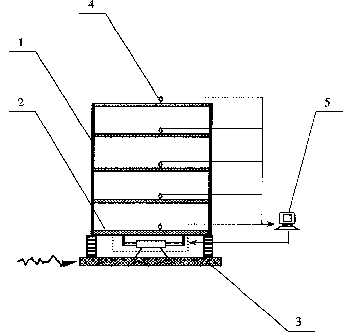
[0020] The vibration isolation energy conversion control device of the present invention is as figure 1 As shown, the bottom of the building structure 1 is composed of the upper base plate 2 of the seismic isolation layer, the lower base plate 3 of the seismic isolation layer, the airbag hydraulic accumulator 6, the overflow valve 7, the three-position four-way electromagnetic reversing valve 8, the hydraulic pressure Oil cylinder 9, hydraulic cylinder piston 10, one-way valve 12-15, and hydraulic tank 16-19 are composed.

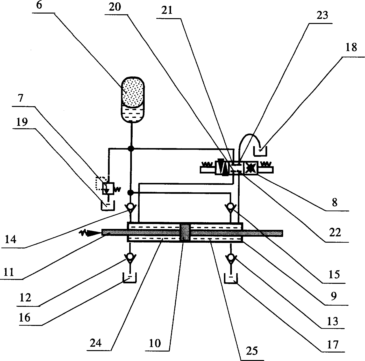
[0021] The internal structure of the transducer is as figure 2 As shown, the hydraulic cylinder 9 is divided into A cylinder 24 and B cylinder 25 by the piston. The A cylinder 24 is connected with check valves 12 and 14. The check valve 12 is connected with the hydraulic tank 16. Device 6 is connected; B cylinder 25 is connected with check valve 13,15, and check valve 13 is connected with hydraulic tank 17, and check valve 15 is connected with air bag typ...

Embodiment 2

[0023] Working status of vibration isolation and energy conversion:

[0024] Such as figure 2 As shown, when the three-position four-way electromagnetic reversing valve 8 is in the middle cut-off position, the oil circuit connected with the three-position four-way electromagnetic reversing valve 8 does not flow. When the structural vibration drives the piston 10 of the hydraulic cylinder 9 to move to the right relative to the hydraulic cylinder 9, the volume of the chamber A 24 increases and the pressure decreases, so that the one-way valve 12 is opened, the one-way valve 14 is closed, and the hydraulic oil is drawn from the hydraulic tank 16 At the same time, the volume of B chamber decreases, the pressure increases, the one-way valve 15 opens, the one-way valve 13 closes, and the hydraulic oil is pressed into the air bag hydraulic accumulator 6 from B chamber 25 , thus realizing the conversion of kinetic energy of structural vibration into hydraulic energy. The flow direc...

Embodiment 3

[0026] Actively control working status:

[0027] According to the needs of structural response information and vibration control, the energy conversion control device can also play a control role, that is, use the high-pressure oil stored in the accumulator 6 as an energy source, and control it by the hydraulic cylinder through the control of the three-way four-position electromagnetic reversing valve 8 9 Apply forces to the structure. The structural response information is transmitted to the computer 5 through the structural response information sensor 4, and the computer 5 controls the operation of the three-way four-position electromagnetic reversing valve 8.

[0028] When the piston 10 of the hydraulic cylinder 9 needs to apply a force to the right, the three-way four-position electromagnetic reversing valve 8 can connect the airbag hydraulic accumulator 6 with the A chamber 24. At this time, the oil pressure of the A chamber 24 is very high. At the same time, the chamber...


PUM


Abstract

The present invention relates to energy converting and vibration controlling device, and is one vibration isolating and energy converting controller comprising vibration isolating layer and energy converter. The vibration isolating layer includes upper board and lower board; the energy converter includes energy converting unit, energy transferring unit and energy accumulating unit; and the energy transferring unit is between the upper board and the lower board of the vibration isolating layer. The present invention can store partial energy of earthquake while isolating earthquake, and the energy may be utilized in active control during passive control.

Description

technical field [0001] The invention relates to an energy conversion and vibration control device, in particular to a vibration isolation energy conversion control device. Background technique [0002] At present, there are many methods applied to structural vibration control, mainly including active control, passive control, semi-active control and hybrid control, etc., but most of these control methods use energy-consuming components to absorb the vibration energy of the structure or use external energy to offset the vibration energy of the structure. , so passive control has unsatisfactory control effect, and energy-consuming components fail due to energy absorption; active control has problems such as large energy required and difficult to realize, and its reliability is not suitable to be guaranteed. The present invention fundamentally solves the above-mentioned problems. Contents of the invention [0003] The obj...

Claims


Application Information

Patent Timeline
Patent Type & Authority Applications(China)
IPC IPC(8): F03G7/08
Inventor 孙作玉程树良
Owner GUANGZHOU UNIVERSITY
Why Eureka
Try Eureka