

Additional mould locking device of indirect extrusion casting
A technology of squeeze casting and additional lock, which is applied in the field of squeeze casting, can solve the problems of casting surface quality degradation, difficult to meet, casting performance degradation, etc., and achieve the effects of reduced residence time, small space, and large clamping force
- Summary
- Abstract
- Description
- Claims
- Application Information
AI Technical Summary
Problems solved by technology
Method used
Image

Examples
Embodiment Construction
[0018] Taking the indirect extrusion casting production of a certain aluminum alloy wheel hub as an example, the present invention is further clarified:
[0019] 1. Squeeze casting equipment
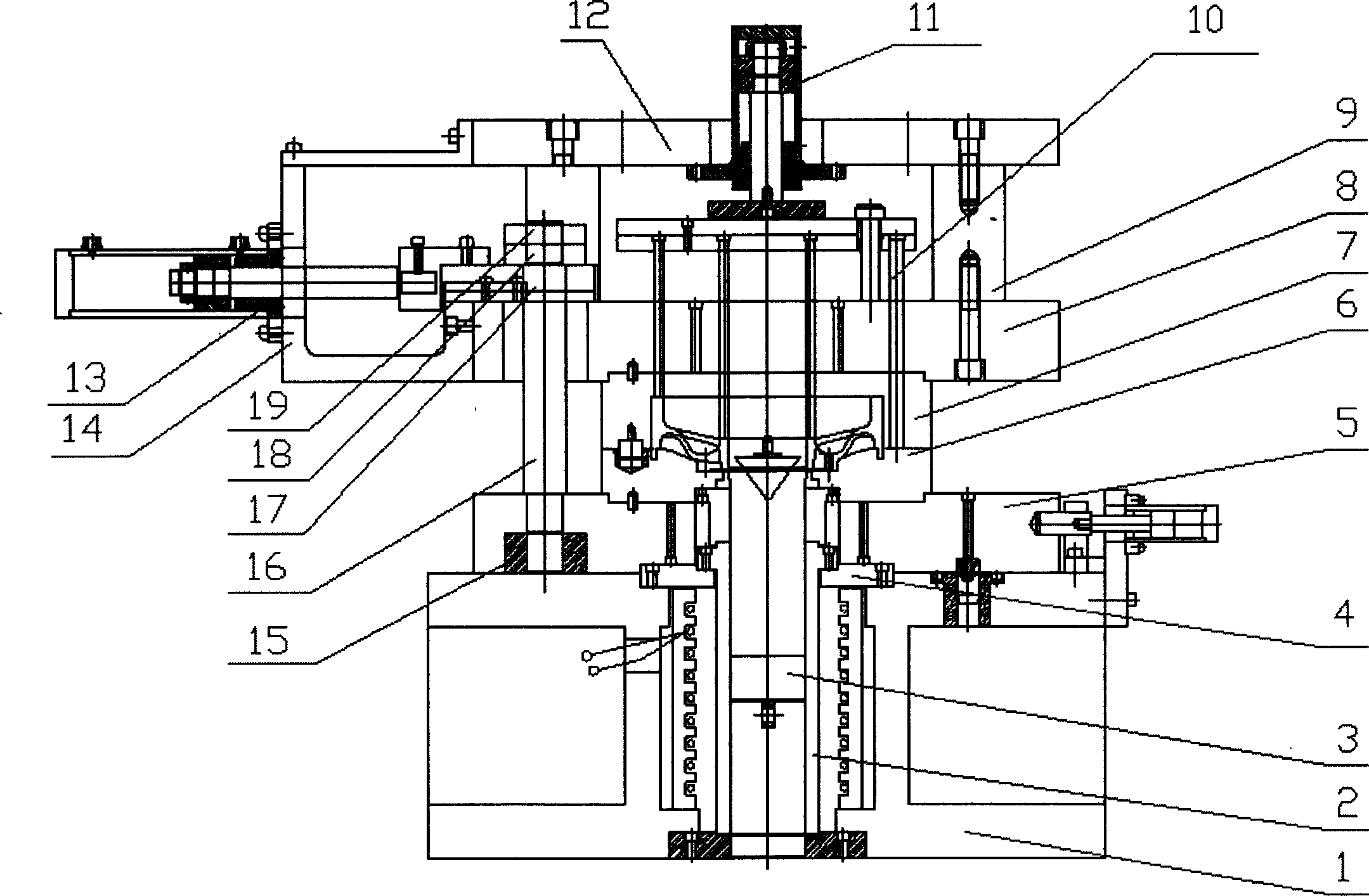
[0020] Hub squeeze casting is carried out on LY-1600 vertical press, such as figure 1 As shown, the base 1 is connected with the working surface of the press by bolts; the extrusion barrel 2 is fixedly connected with the base 1 through the fixed flange 4; the extrusion head 3 is fixedly connected with the lower cylinder of the press; the lower mold base 5 is connected with the base 1 Contact fit, but no fixed connection; the lower mold 6 is fixedly connected with the lower mold base 5, and the upper mold 7 is fixedly connected with the upper mold base 8; the upper mold base 8 is fixedly connected with the upper mold connecting plate 12 through the connecting column 9; The upper die connecting plate 12 is fixedly connected with the upper cylinder of the press.
[0021] 2. Additional cla...
PUM
 Abstract
Description
Claims
Application Information