Building exterior-protected construction heat transfer coefficient on-site detecting method

A technology of enclosure structure and heat transfer coefficient, applied in the direction of thermal conductivity of materials, calorimeters, measuring devices, etc., can solve the problems of project completion acceptance, difficulty in detection work, and concentrated workload, so as to reduce labor intensity and improve The effect of shortening the equipment utilization rate and detection cycle

Inactive Publication Date: 2006-01-18
GANSU BUILDING MATERIALS DESIGN & RES INST CO LTD +1
View PDF0 Cites 22 Cited by
  • Summary
  • Abstract
  • Description
  • Claims
  • Application Information

AI Technical Summary

Problems solved by technology

However, the actual situation is that most construction projects are completed in summer and autumn. If they wait until winter heating for inspection, the time and workload will be concentrated during this period, which will inevitably bring difficulties to the inspection work; Acceptance will also have a certain impact

Method used


Image

  • Building exterior-protected construction heat transfer coefficient on-site detecting method
  • Building exterior-protected construction heat transfer coefficient on-site detecting method
  • Building exterior-protected construction heat transfer coefficient on-site detecting method

Examples


Embodiment 1

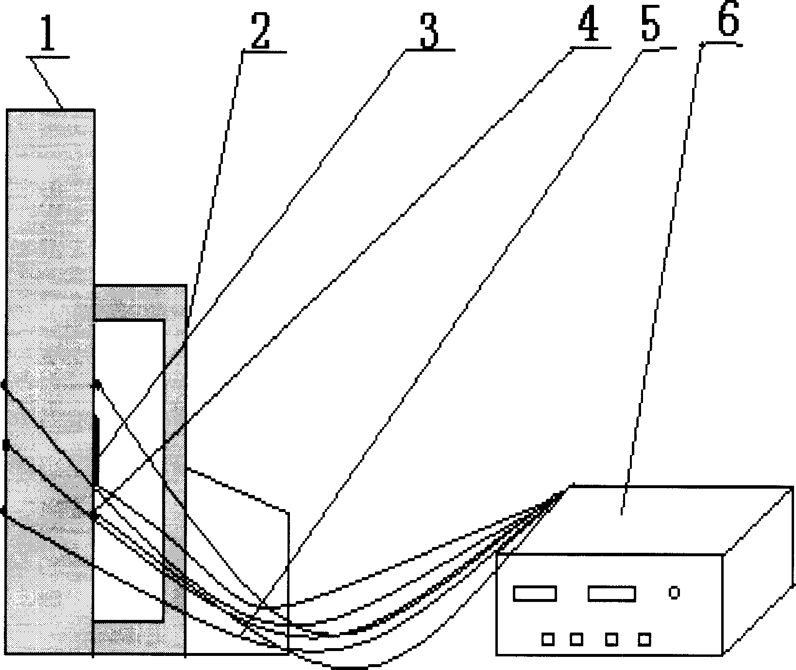
[0027] Embodiment 1 Referring to the accompanying drawings, the surface of the heat flow meter 3 is coated with a thin and uniform butter layer, so that the heat flow meter 3 can be stuck on the surface of the wall body 1 to be measured, and then squeezed from the center of the heat flow meter 3 to the outer edge to eliminate For air bubbles between the heat flow meter 3 and the wall 1, wipe off the stains on the surface of the heat flow meter 3 after pasting, and fix it on the surface of the wall 1 with plastic tape. The temperature sensor 4 is pasted on both sides of the wall body 1 in the measured area with double-sided adhesive tape, that is, the temperature sensor 4 on the inner side is close to the heat flow meter 3, and the temperature sensor 4 on the outer surface is pasted on the position corresponding to the heat flow meter 3, and distributed uniform. Then, the heat flow meter 3 and the temperature sensor 4 are connected to the temperature and heat flow automatic cir...

Embodiment 2

[0038] Embodiment 2 The present invention compares the detection of the heat transfer coefficient of a certain room's outer wall in the non-heating period with the routine detection in the heating period.

[0039] Operation method is the same as embodiment 1.

[0040] Detection is divided into manual temperature control detection and heating period detection

[0041] 1. Manual temperature control detection

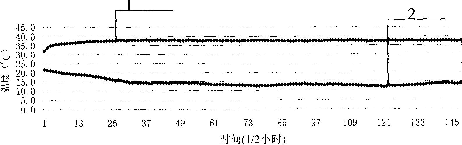
[0042] The present invention adopts opening 1×1m 2 Automatic temperature control incubator 2 (heating), test result with figure 2 ,

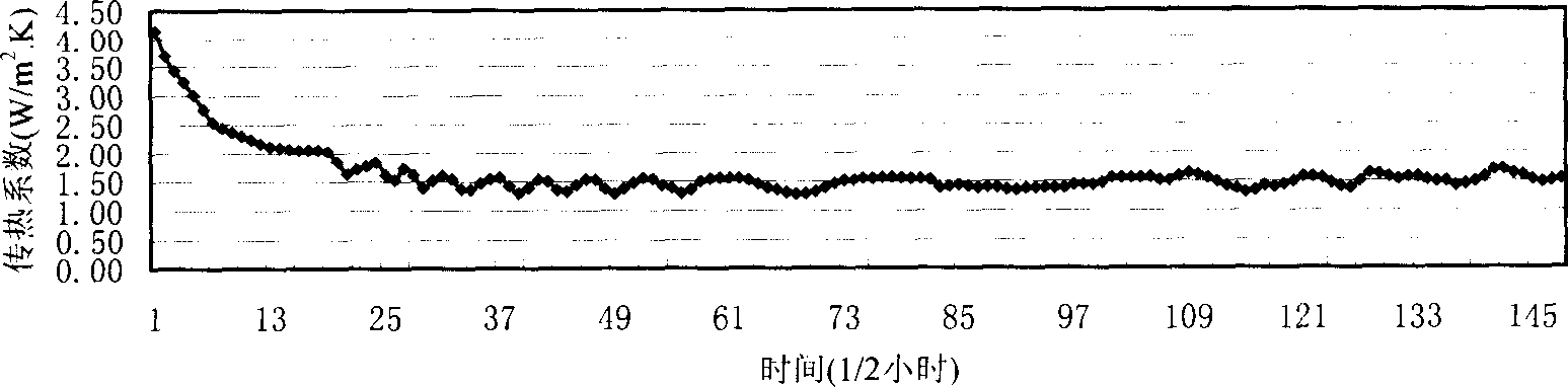
[0043] image 3 Expressed in graph form.

[0044] The horizontal axis is the continuation of the detection time, each counting unit is 0.5h, and the vertical axis represents the heat transfer coefficient (W / m 2.K. ). It can be seen from the curve that the value of the heat transfer coefficient is relatively stable, and it reaches stability relatively quickly, and it begins to stabilize around the 30th point, that is, it begins to st...


PUM


Abstract

The invention relates to an architecture exterior-protected construction heat transfer rate on-site detection method which comprises: attaching heat flow meter and temperature sensor, connecting heat flow meter, temperature sensor and temperature heat flow automatic patrol testing equipment by transmission line, attaching automatic temperature-controller with the inner wall which has heat flow meter and temperature sensor, adjusting automatic temperature-controller, automatically reading storage measuring value, computing architecture exterior-protected construction heat transfer rate. It uses differential temperature measured by temperature sensor and electromotance E outputted by heat flow meter to reflect heat flow density. It uses formula to compute heat transfer rate K.

Description

technical field [0001] The invention relates to a detection method for building envelope structures, in particular to a field detection method for the heat transfer coefficient of building envelope structures. Background technique [0002] At present, my country is in the heyday of construction industry development. From 1990 to 2002, the average annual growth rate of the building area under construction and completion in my country was as high as 155%. With the rapid growth of the building area, people's requirements for the comfort of the indoor environment are constantly improving. In winter, the room temperature is raised from 12°C-16°C to 18°C-20°C; in summer, the room temperature is reduced from 30°C to 22°C-20°C. According to estimates, in recent years, my country's building energy consumption has accounted for more than 25% of the total social energy consumption, and the heating energy consumption in the northern region has exceeded 40% of the local social total en...

Claims


Application Information

Patent Timeline
Patent Type & Authority Applications(China)
IPC IPC(8): G01N25/18G06F19/00
CPCG01K17/20
Inventor 田斌守杨永恒张镛段兆瑞曹万智侯文虎
Owner GANSU BUILDING MATERIALS DESIGN & RES INST CO LTD
Why Eureka
Try Eureka