A medium voltage vacuum contactor

A vacuum contactor and medium-voltage technology, which is applied in high-voltage air circuit breakers, stepless relays, high-voltage/high-current switches, etc., can solve the problems of mutual positioning defects of contacts, affecting the electrical life of contactors, leakage, etc.

Inactive Publication Date: 2006-01-18
ABB (SCHWEIZ) AG
View PDF0 Cites 6 Cited by
  • Summary
  • Abstract
  • Description
  • Claims
  • Application Information

AI Technical Summary

Problems solved by technology

These solutions, in addition to causing the overall bulkiness of the mechanism, also negatively affect the electrical life of the contactor, especially the vacuum contactor
In fact, in this particular contactor, the contacts are coupled head-by-head; therefore, the mechanism m...

Method used


Image

  • A medium voltage vacuum contactor
  • A medium voltage vacuum contactor
  • A medium voltage vacuum contactor

Examples


Embodiment Construction

[0018] Figure 5 with Image 6 A three-pole medium voltage vacuum contactor is shown, generally indicated by reference numeral 100 . Each pole of the contactor 100 has a vacuum shell 1, such as a vacuum cover or a vacuum spherical shell, which contains a fixed contact 2 and a corresponding movable contact 3, for the sake of simplicity, only one pole is given A diagram is shown; the possible structural implementation of the vacuum housing 1 and the way of maintaining the vacuum therein are well known in the art, and thus will not be described in detail. According to a well-known solution, each movable contact 3 is connected to an actuating lever 4 to which is associated a contact compression spring 5 .

[0019] The contactor 100 also includes an actuating device, which is operatively connected to the movable contact 3 and provides for moving the movable contact 3 and allowing the movable contact 3 to operate relative to the corresponding fixed contact. Point 2 Electrically c...


PUM


Abstract

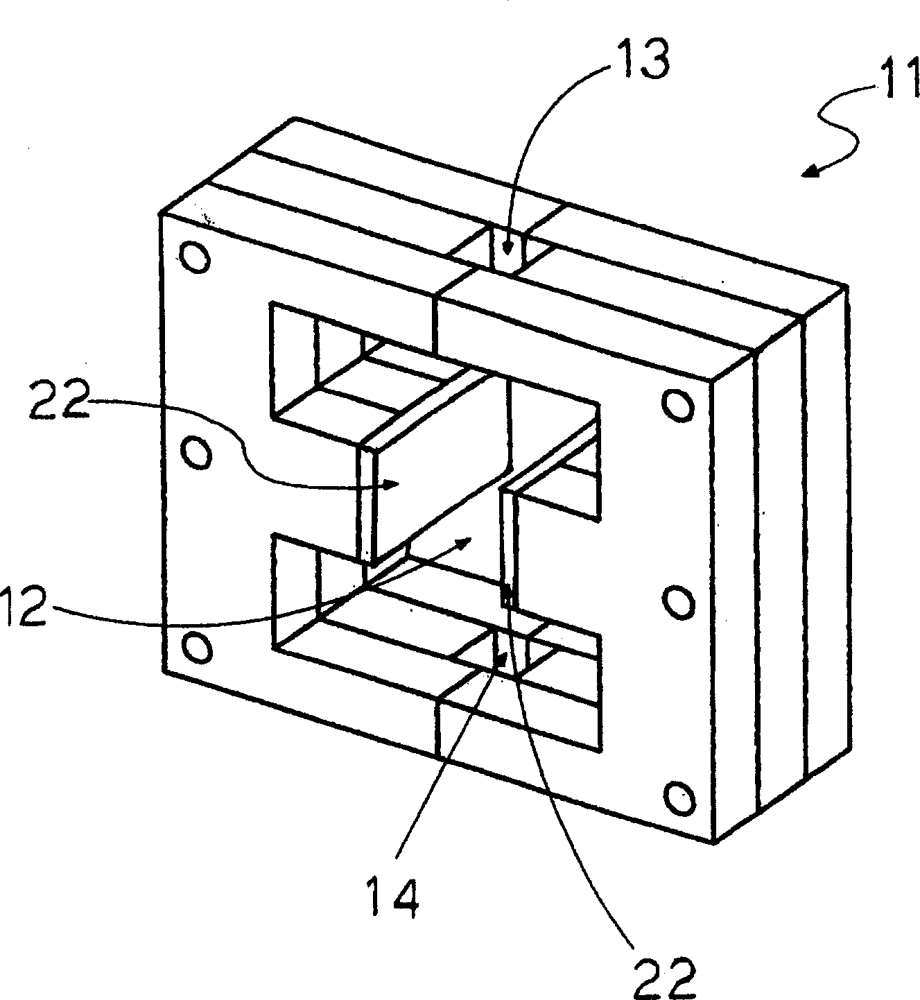
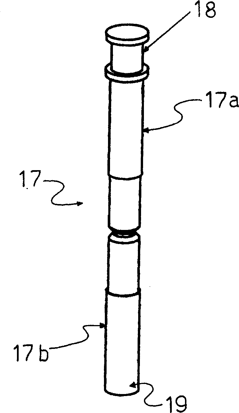
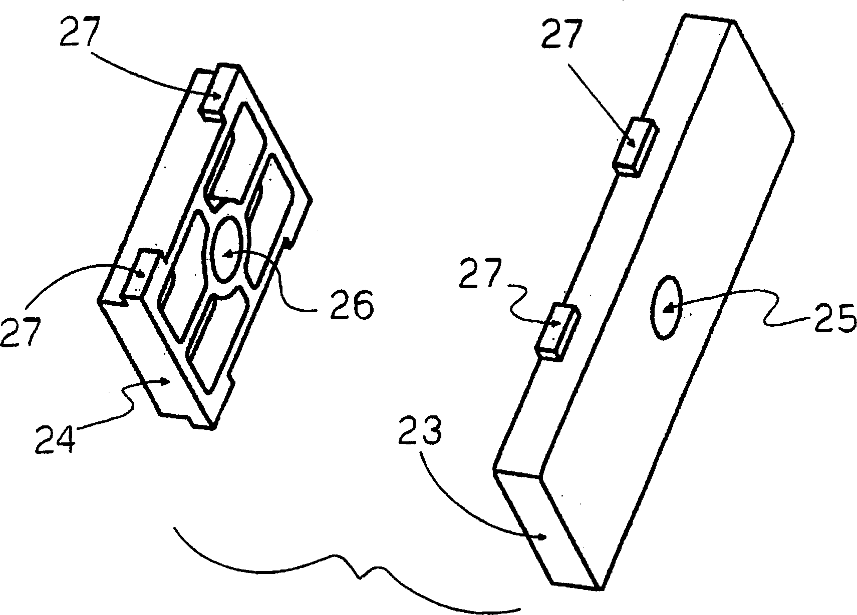
A medium voltage vacuum contactor comprising for each pole, a vacuum envelope which contains a fixed contact and a corresponding movable contact; and actuating means providing the energy required to move the movable contacts, characterized in that said actuating means comprise an electromagnetic actuator having: a magnetic yoke which has an inner cavity communicating with the outside through at least a first opening; at least one coil accommodated in the cavity; a movable armature which is operatively connected to at least one movable contact through coupling means, and is mounted axially displaceable in the cavity with at least one end protruding from the first opening; at least one permanent magnet devoted to directly hold the movable armature in two stable positions. Further, there are provided means for guiding the movement of the movable armature which are positioned outside the yoke in correspondence of at least the first opening.

Description

technical field [0001] The present invention relates to a medium voltage vacuum contactor, preferably for applications with an operating voltage between 3 and 12 kV, with improved functions and features. Background technique [0002] It is known to use two different types of switching devices in power systems; the first type consists of so-called protective devices, typically circuit breakers, whose main purpose is to operate for a specific period of time in the event of a specific abnormal circuit condition, i.e. a short circuit. Carry current and then break current; the second consists of an operational switching device such as the contactor of the present invention, capable of making, carrying and breaking current under normal circuit conditions including overload conditions. [0003] These contactors, which are widely used for example to switch electric motors, need to meet several conditions which are important to guarantee the correct performance of the contactor durin...

Claims


Application Information

Patent Timeline
IPC IPC(8): H01H33/66H01H51/01
CPCH01H33/6662
Inventor 奥斯瓦尔多·普雷斯蒂尼阿尔贝托·祖拉蒂
Owner ABB (SCHWEIZ) AG
Why Eureka
Try Eureka