Method for preventing send buffer overflow of radio link control layer

A wireless link control and buffer technology, which is applied in the communication between multiple stations, can solve the problems of complex timer management and low efficiency of sending data, and achieve the effects of simple method, improved efficiency and reduced number

Active Publication Date: 2006-01-18
LEADCORE TECH
View PDF0 Cites 6 Cited by
  • Summary
  • Abstract
  • Description
  • Claims
  • Application Information

AI Technical Summary

Problems solved by technology

[0020] The object of the present invention is to provide a kind of method that realizes simple, high-efficiency prevents the transmission buffer overflow of radio link control layer, to solve existing in the prior art because RLC layer distributes a discarding timer to each SDU, thereby The technical problems that lead to complex management of timers in RLC and the resulting low efficiency of sending data

Method used


Image

  • Method for preventing send buffer overflow of radio link control layer
  • Method for preventing send buffer overflow of radio link control layer
  • Method for preventing send buffer overflow of radio link control layer

Examples


Embodiment Construction

[0033] Hereinafter, the present invention will be described in detail with reference to the drawings.

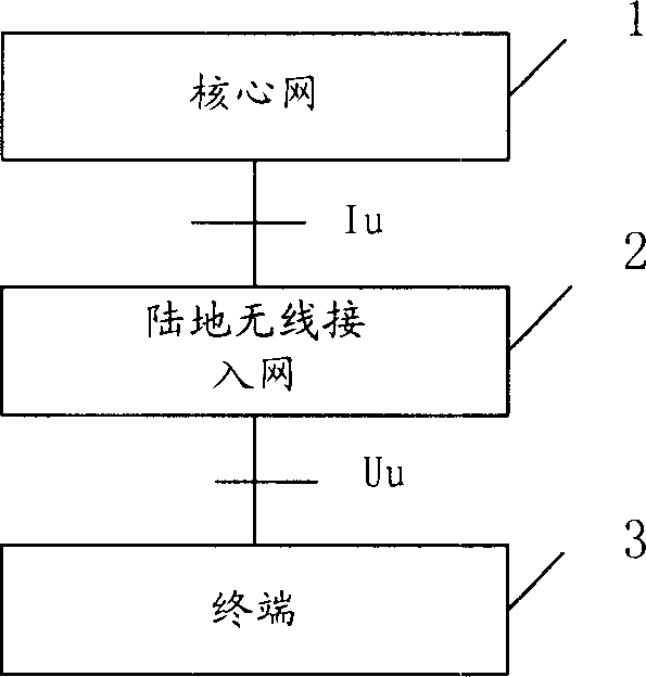
[0034] The present invention is applicable to a wireless communication transmission system using an air interface protocol, and the system includes a TD-SCDMA (Time Division Synchronous Code Division Multiple Access) communication system.

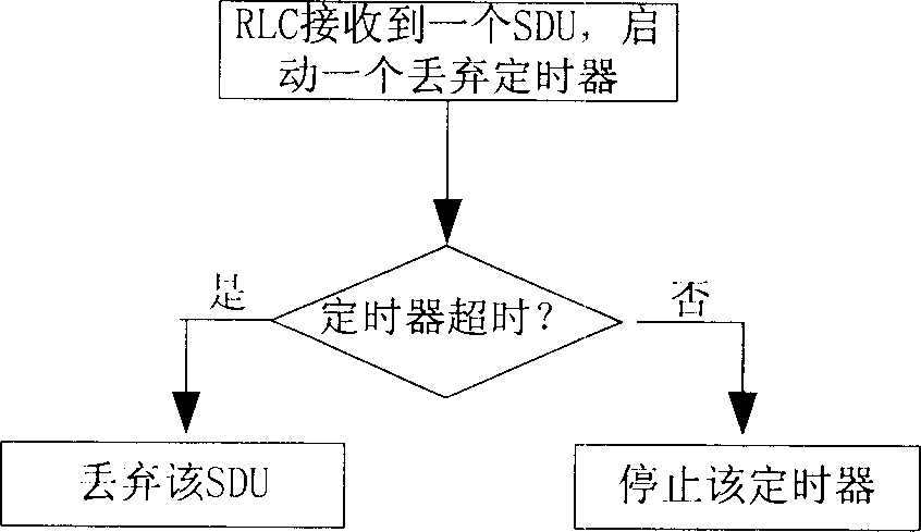
[0035] Please refer to FIG. 4 , which is a flow chart of the present invention to prevent overflow of the transmit buffer of the RLC layer. The sending buffer is used to store the service data unit SDU sent by the upper layer, including the following steps:

[0036] S210: The radio link control layer RLC obtains the maximum allowed buffering time of each SDU sent by the upper layer and the receiving time of each SDU, and stores them in the sending buffer according to the receiving time sequence of the SDUs;

[0037] When RLC receives each SDU, it saves the maximum time allowed for the SDU to be buffered, and this time is recorded as T1. T1...


PUM


Abstract

This invention discloses a method for preventing the transmitting buffer of the wireless links controlling layer overflowing, wherein the transmitting buffer is used for storing the SDU. The method comprises the following steps: A) the wireless links controlling layer will get the maximum buffer time T1 of every SDU which is transmitted by the upper layer, and get the receiving time of said SDU T2; storing to the transmitting buffer according to the receiving order of SDU; B: after a presetting cycle, according to the maximum buffer time and receiving time, the RLC will test the SDU which is stored in the transmitting buffer, and deserting the overdue SDU. Said invention decreases the intervalometer numbers used by the RLC greatly; and it only need to compute and compare some SDU in the transmitting buffer to desert the overdue SDU.

Description

technical field [0001] The invention relates to a wireless communication transmission system, in particular to a method for sending data by a wireless link control layer in the wireless communication transmission system. Background technique [0002] Currently, the Universal Mobile Telecommunications System (UMTS) is introduced into the wireless communication transmission system. see figure 1 , which is a simplified structure diagram. It mainly consists of three parts: core network 1 (CN), terrestrial radio access network 2 (UTRAN) and terminal 3 (UE). A connection is made between the terminal 3 and the terrestrial wireless access network 2 through Uu (wireless interface, also called an air interface). In order to achieve the purpose of communicating with each other, the same air interface protocol is adopted between the air interfaces. [0003] see figure 2 , which is the architecture of the air interface protocol. It is mainly divided into three layers, the lowest l...

Claims


Application Information

Patent Timeline
IPC IPC(8): H04B7/26
Inventor 张瑛
Owner LEADCORE TECH
Why Eureka
Try Eureka