Medicine supplying apparatus
A technology for supplying devices and medicines, which is applied in the direction of making medicines into special physical or taking forms, packaging, transportation and packaging, etc., which can solve the problem of clogging medicines and achieve the effect of eliminating bridging phenomenon
- Summary
- Abstract
- Description
- Claims
- Application Information
AI Technical Summary
Problems solved by technology
Method used
Image
Examples
Embodiment 1
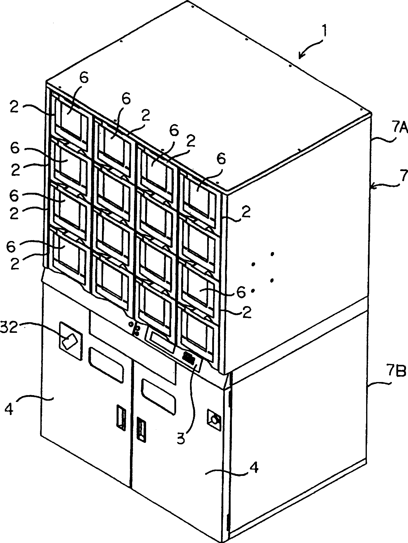
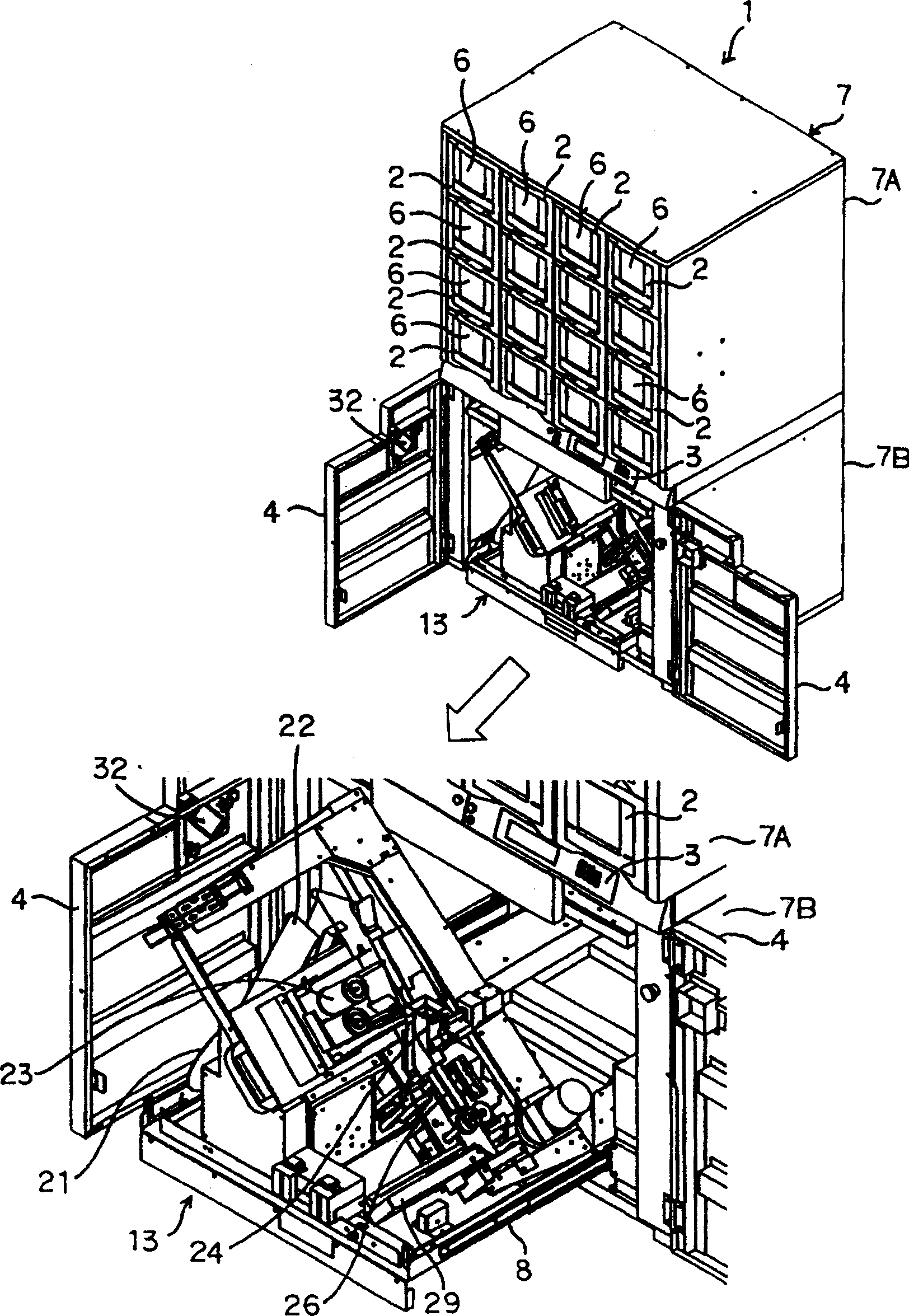
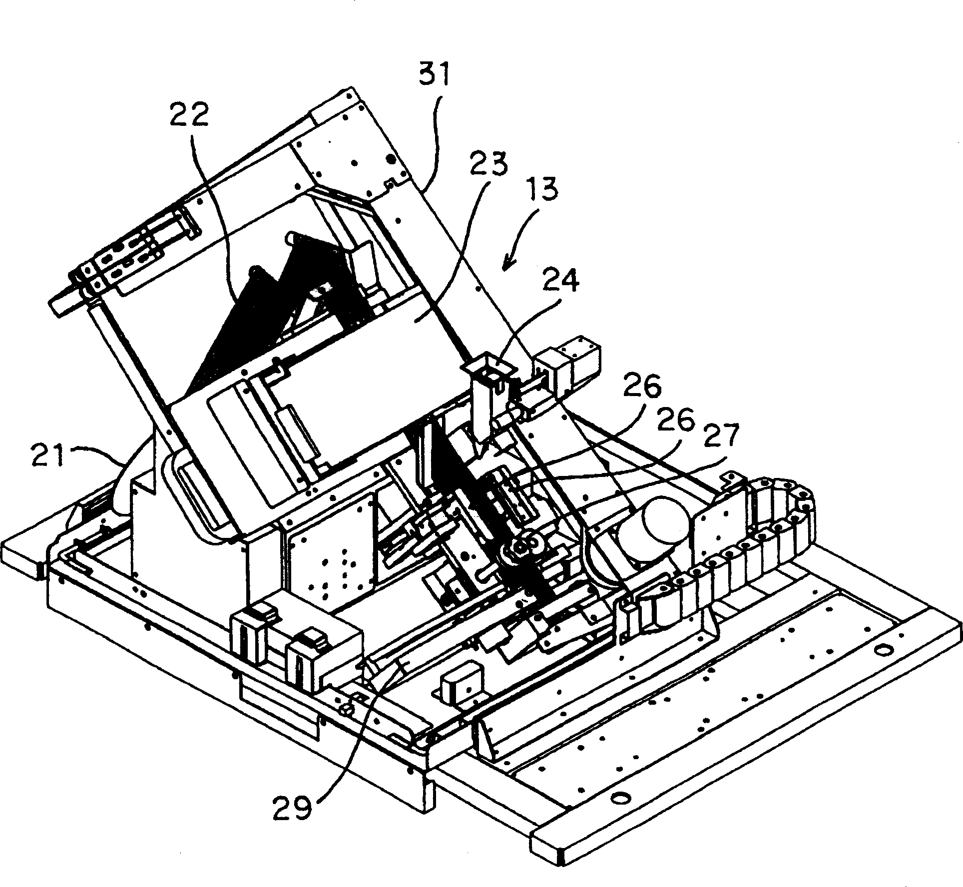
[0036] figure 1 is a perspective view of a medicine supply device 1 according to an embodiment of the present invention, figure 2 is a perspective view of the medicine supply device 1 in a state where the lower plate 4 is opened, image 3 It is a perspective view of the packaging machine 13 of the medicine supply device 1 .
[0037]The medicine supply device 1 of this embodiment is installed in a hospital, a dispensary, etc., and is composed of a rectangular main body 7 whose length is the vertical direction, a computer for control described later, and the like. The main body 7 is composed of, for example, an upper structure body 7A and a lower structure body 7B which can be separated from each other, and has a structure in which the upper structure body 7A is laminated and connected to the lower structure body 7B. In addition, in this upper structure 7A, a box storage portion arranged forward and opened downward is formed for storing unshown tablet boxes, and medicines are...
Embodiment 2
[0074] Secondly, Figure 10 Shown is the cross section of the nozzle 24 of another embodiment of the invention. At this time, the roller 9 is attached to the position where the narrow portion 33 of the wall 24B on the inner side of the mouth 24 starts, that is, the position where the medicine drop passage 34 is narrowed, and a part of it faces inside the medicine drop passage 34 . Also, if the shutter 37 is centered on the drive shaft 38 through the solenoid 41 Figure 10 Rotate counterclockwise (open) in the same figure, then the roller 9 will rotate a specified angle in the counterclockwise direction in the same figure, and the shutter 37 will rotate clockwise (closed), at this time, the roller 9 is indicated by the arrow in the same figure Rotate the specified angle clockwise as indicated.
[0075] Then, when the shutter 37 is opened and the medicine D falls as it is in the horizontal posture, it falls as it is. Figure 10 When the state between the wall 24A of the mouth...
Embodiment 3
[0077] Secondly, Figure 11 It is a cross section showing another mouthpiece 24 of the medicine supply device 1 of the present invention. At this time, the roller 9 is not provided, and instead, a protruding portion 24C facing the shutter 37 is formed on the wall surface 24A of the barrel mouth 24 facing the upper portion of the shutter 37 (approximately at the same height as the drive shaft 38). The upper surface of the protruding portion 24C is inclined toward the direction (inward side) of the shutter 37 at a gentle slope to a lower position.
[0078] According to the above composition, in the Figure 11 In the closed state of the shutter 37 shown by the middle dotted line, when the large-sized medicine D rack stops between the protrusion 24C and the shutter 37, if the shutter 37 is opened, the side of the wall 24A of the medicine D is blocked. Since the protruding part 24C is supported, the medicine D will drop down from the side of the shutter 37 along with it. Thereby...
PUM
 Abstract
Description
Claims
Application Information
 - R&D
- Intellectual Property
- Life Sciences
- Materials
- Tech Scout
- Unparalleled Data Quality
- Higher Quality Content
- 60% Fewer Hallucinations
Browse by: Latest US Patents, China's latest patents, Technical Efficacy Thesaurus, Application Domain, Technology Topic, Popular Technical Reports.
© 2025 PatSnap. All rights reserved.Legal|Privacy policy|Modern Slavery Act Transparency Statement|Sitemap|About US| Contact US: help@patsnap.com


