Carbon heater

A carbon heater and heater technology, applied in heating elements, ohmic resistance heating, heating element shape and other directions, can solve the problem of radiant energy not being emitted evenly, achieve the effect of firm carbon filament support structure and improve service life

Inactive Publication Date: 2006-02-15
LG ELECTRONICS INC
View PDF0 Cites 5 Cited by
  • Summary
  • Abstract
  • Description
  • Claims
  • Application Information

AI Technical Summary

Problems solved by technology

As a result, radiant energy is not emitted evenly from the carbon heater in all directions

Method used


Image

  • Carbon heater
  • Carbon heater
  • Carbon heater

Examples


Embodiment Construction

[0036] Now, some preferred embodiments of the present invention will be described in detail with reference to the accompanying drawings.

[0037] Figure 4 is a longitudinal sectional view showing the main parts of the carbon heater according to the first preferred embodiment of the present invention.

[0038] Such as Figure 4 As shown, the carbon heater according to the first preferred embodiment of the present invention includes: a quartz tube 50, a tube seal 51 is formed at both ends of the quartz tube; Used as a heating element, the carbon wire 52 is formed into a twisted sheet shape; external electrodes 56 are respectively provided on the tube seals 51 of the quartz tube 50 and exposed to the outside of the quartz tube 50; metal wires 55 are respectively fixed by Metal pieces 58 to tube seal 51 at both ends of quartz tube 50 are connected to external electrodes 56; and connection conductors 54 are connected between both ends of carbon wire 52 and metal wire 55, respect...


PUM


Abstract

Disclosed herein is a carbon heater. The carbon heater comprises a sheet-shaped carbon filament disposed in a tube. The carbon filament is arranged in the tube while being twisted. Consequently, radiant heat is uniformly emitted in all directions. Furthermore, support parts are formed at the twisted sheet-shaped carbon filament or support wires are attached to the twisted sheet-shaped carbon filament, whereby the filament support structure is more secured. Consequently, the service life of the carbon heater is increased, and easy design and assembly of the carbon heater are accomplished.

Description

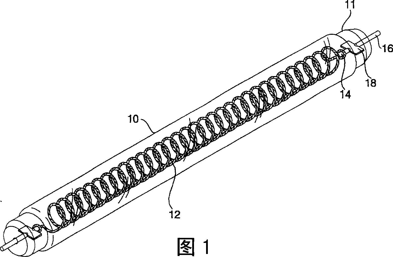
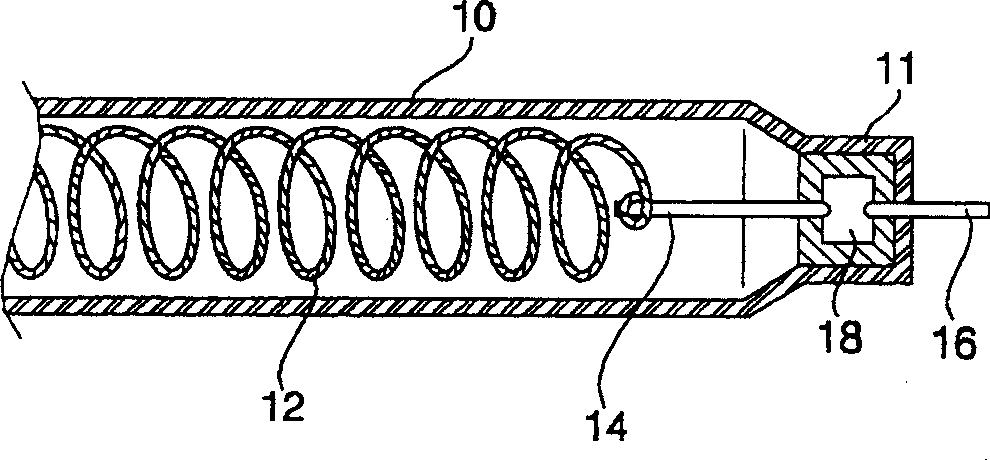
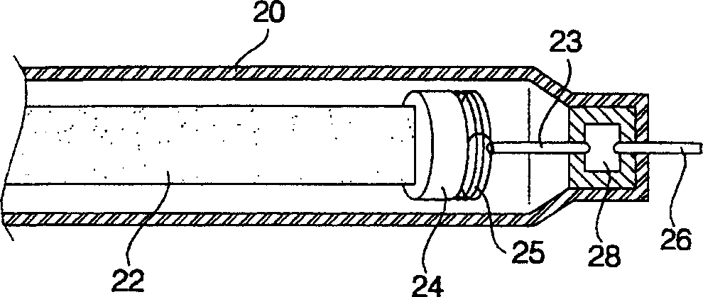
technical field [0001] The present invention relates to a carbon heater comprising carbon fibers or filaments used as heating elements, and more particularly to a carbon heater having carbon filaments in the form of sheets twisted and placed in a tube , thus achieving uniform radiation in all directions and having a strong carbon filament support structure. Background technique [0002] Generally, a carbon heater is a heater that uses a filament made of carbon as a heating element. As we all know, carbon heaters have good thermal efficiency, carbon will not harm the environment when it is discarded, and can provide many functions, such as far-infrared radiation, deodorization, disinfection, and antibacterial activity, etc., so carbon heaters have been increasingly used. It is widely used in room heating and drying equipment, as well as in heating equipment. [0003] Fig. 1 is a perspective view showing a conventional helical carbon heater, figure 2 is a longitudinal secti...

Claims


Application Information

Patent Timeline
Patent Type & Authority Applications(China)
IPC IPC(8): H05B3/44H05B3/46H05B3/06
CPCH05B2203/032H05B3/009H05B3/04H05B3/44H05B3/145H05B3/14
Inventor 金完洙金亮卿李荣峻
Owner LG ELECTRONICS INC
Why Eureka
Try Eureka