Heat pipe vacuum sealing method and apparatus thereof

A vacuum sealing and vacuum sealing technology, which is applied in the direction of hollow objects, indirect heat exchangers, heat exchange equipment, etc., can solve the problems of unguaranteed heat pipe packaging quality, waste of materials in the packaging form, and influence on the use of heat pipes, and achieve simple structure and improved efficiency. Improvement in productivity and packaging quality

Inactive Publication Date: 2006-02-22
林项武
View PDF0 Cites 23 Cited by
  • Summary
  • Abstract
  • Description
  • Claims
  • Application Information

AI Technical Summary

Problems solved by technology

The productivity is low, and the quality of heat pipe packaging cannot be guaranteed. At the same time, the packaging form of the end not only wastes materials, but also has a certain impact on the use of heat pipes.

Method used


Image

  • Heat pipe vacuum sealing method and apparatus thereof
  • Heat pipe vacuum sealing method and apparatus thereof
  • Heat pipe vacuum sealing method and apparatus thereof

Examples


Embodiment Construction

[0021] Below in conjunction with accompanying drawing and specific embodiment the present invention is described in further detail:

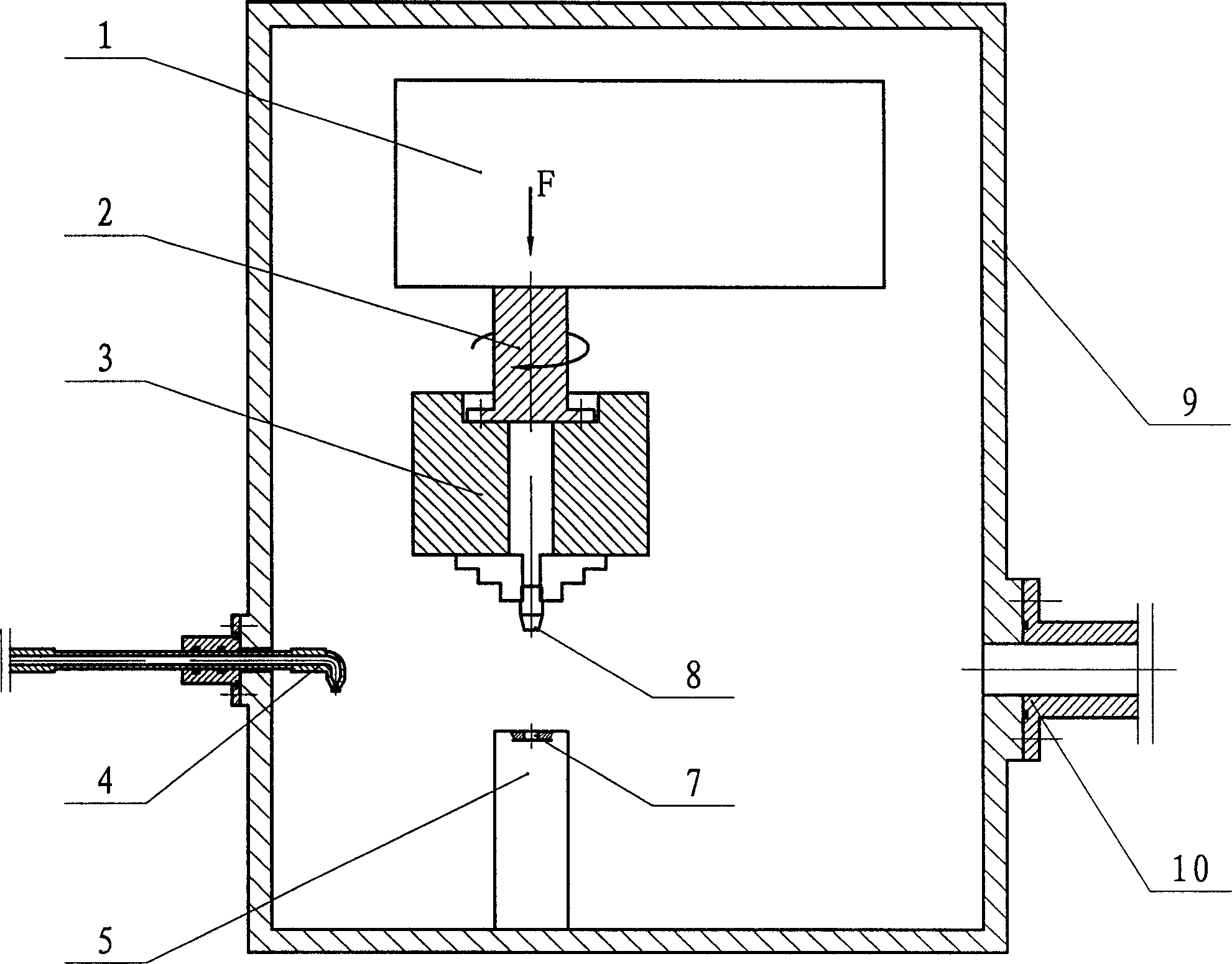
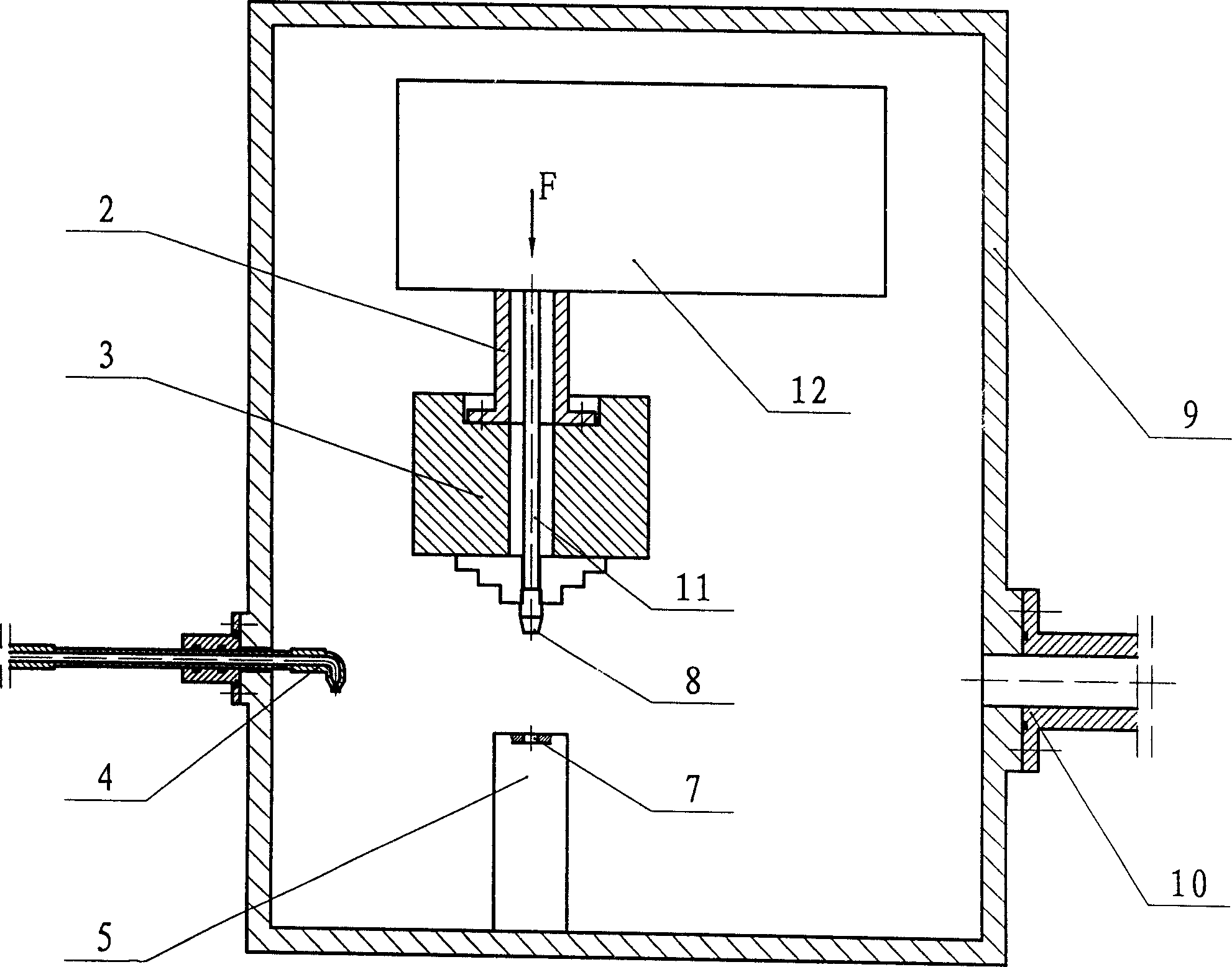
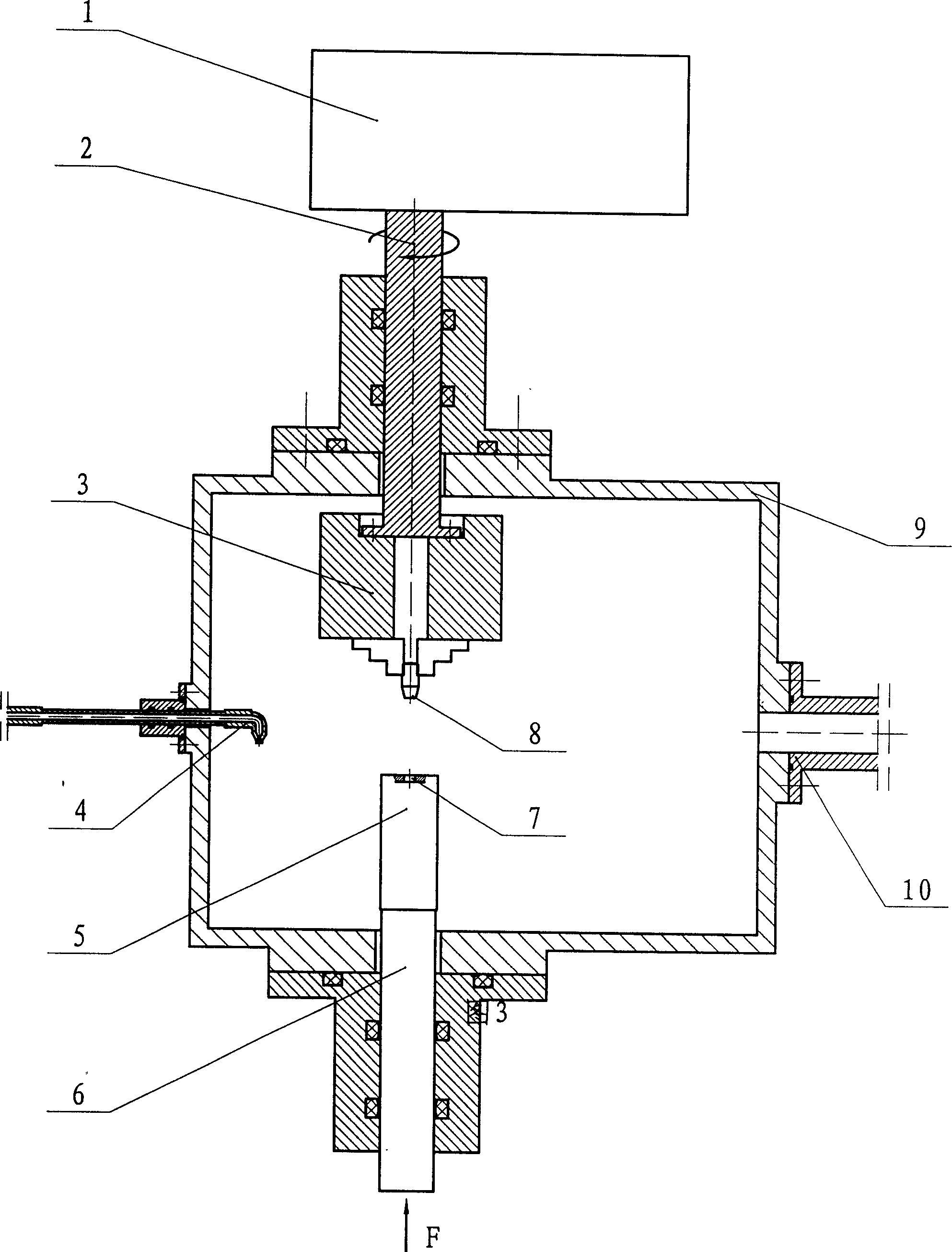
[0022] A heat pipe vacuum sealing method, the heat pipe to be packaged reserves a sealing hole 7, completes the process of vacuuming and liquid filling in a vacuum chamber 9, and applies friction welding 1 or ultrasonic welding 12 to weld the sealing plug 8 to the reserved sealing 7 and form a tight weld.

[0023] The sealing plug 8 may be one of a cylinder, a cone, a T-shaped body of revolution, and a body of revolution whose free end is smaller than the clamped end and whose generatrix transitions smoothly.

[0024] In the heat pipe vacuum sealing method described above, the reserved seal 7 may be one of a cylindrical hole, a conical hole, and a counterbore.

[0025] A heat pipe vacuum sealing device, including a vacuum generating system, a heat pipe to be packaged and its positioning and clamping system 5, a liquid filling system, a sealing ...


PUM


Abstract

This invention relates to a heat pipe vacuum sealing method and device, characterized in that it uses heat transfer agent heat exchanging equipment to seal. The sealing method comprises the following steps: a) preparing the sealing hole in the heat pipe to be sealed; b) evacuating and charging pump in vacuum chamber; c) welding the sealing to the prepared sealing hole by the friction welding or ultrasonic welding, forming sealing welding. The sealing device comprises vacuum generating system, a heat pipe to be sealed, an orientation fasten system and a prefilling system, wherein the heat pipe and the orientation fasten system are set in the vacuum chamber, after evacuating and prefilling, the fasten system will grasp the sealing block to the sealing hole to weld.

Description

technical field [0001] The invention relates to a heat pipe vacuum sealing method and device, in particular to a sealing method and device using intermediate heat transfer medium heat exchange equipment. Background technique [0002] "Heat Pipe Technology and Its Engineering Application" (ISBN 7-5025-2752-4 / TQ.1212) describes several commonly used heat pipe vacuum sealing methods and devices. The method is to vacuumize the reserved seal of the heat pipe to be packaged through the capillary, inject the working medium after reaching the vacuum degree required by the process, and immediately flatten the capillary to seal, and then weld. The heat generated during the welding process can easily make the working medium exceed its working temperature, produce non-condensable gas, and even make the heat pipe scrapped. The productivity is low, and the quality of heat pipe packaging cannot be guaranteed. At the same time, the packaging form of its end not only wastes materials, but a...

Claims


Application Information

Patent Timeline
Patent Type & Authority Applications(China)
IPC IPC(8): F28D15/02B23K20/10B23K20/12B23K101/14
CPCF28D15/0283
Inventor 林项武
Owner 林项武
Why Eureka
Try Eureka