Electro-optical device, color filter, and electronic apparatus

A technology of electro-optical devices and color filters, applied in the direction of electric solid-state devices, instruments, circuits, etc., can solve the problem that the pixel arrangement structure cannot be used

Inactive Publication Date: 2006-02-22
SEIKO EPSON CORP
View PDF2 Cites 27 Cited by
  • Summary
  • Abstract
  • Description
  • Claims
  • Application Information

AI Technical Summary

Problems solved by technology

But, in the occasion of carrying out this multi-primary color display, because the pixel arrangement structure described in the above-m

Method used


Image

  • Electro-optical device, color filter, and electronic apparatus
  • Electro-optical device, color filter, and electronic apparatus
  • Electro-optical device, color filter, and electronic apparatus

Examples


Embodiment Construction

[0039] Hereinafter, embodiments of the present invention will be described with reference to the drawings.

[0040] In addition, in all the following drawings, since each layer or each member is formed in the magnitude|size which can be recognized on drawing, the scale differs with respect to each layer or each member.

[0041] (first embodiment)

[0042]Hereinafter, with regard to the first embodiment of the present invention, refer to figure 1 Go to FIG. 4 for description.

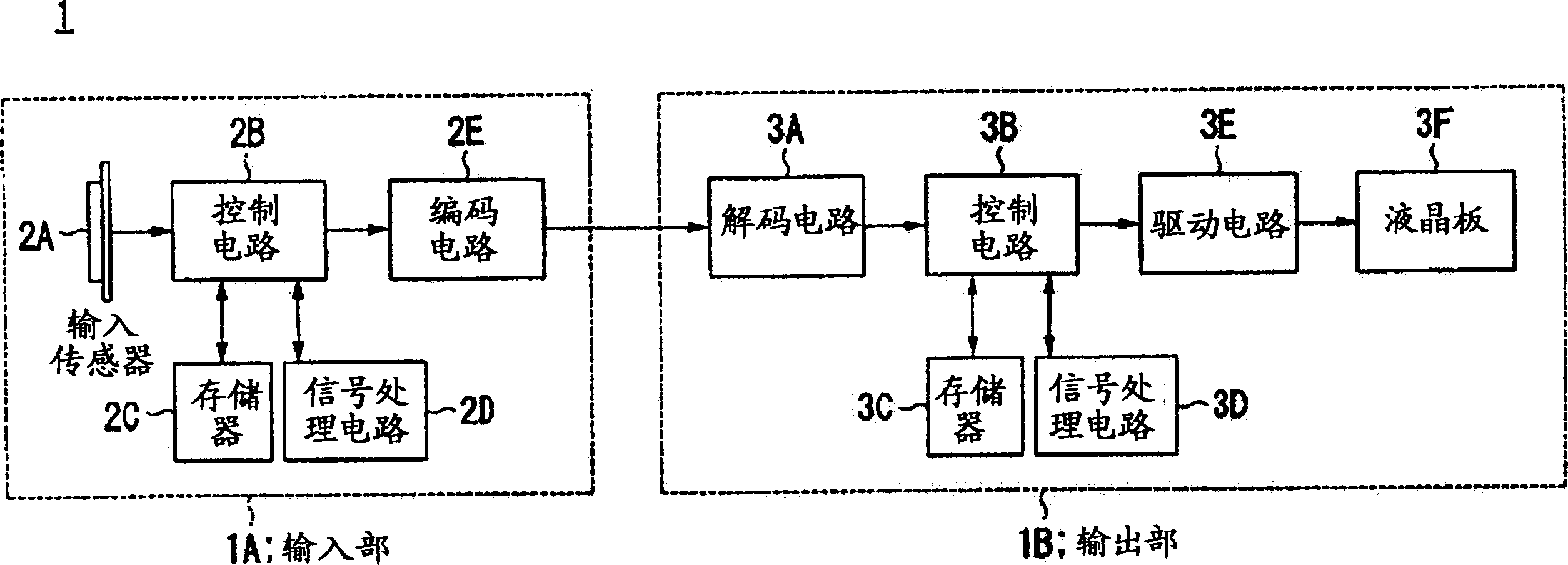
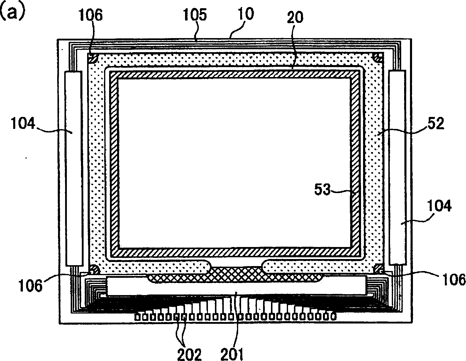
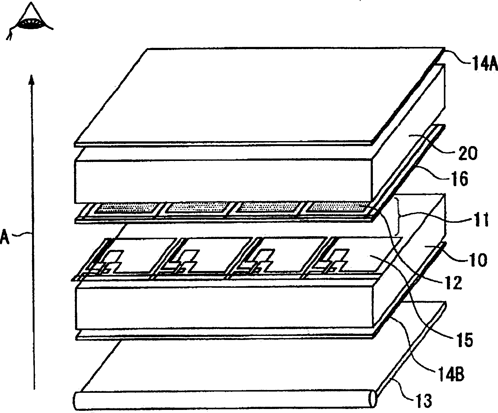
[0043] figure 1 is a block diagram showing the configuration of the image display system of this embodiment, figure 2 It is a plan view of each constituent element of a liquid crystal panel included in an image display system viewed from the opposing substrate side, image 3 is an exploded perspective explanatory diagram showing a liquid crystal panel included in an image display system, and Fig. 4 is image 3 The plan view of the color filter shown in .

[0044] figure 1 The image display system...


PUM


Abstract

The invention provides an electro-optical device for five-primary-color display with a novel pixel arrangement structure, high definition and high image quality. The inventive electro-optical device comprises a display area formed by the planar arrangement of a plurality of display pixels, a plurality of sub-pixels (corresponding to colored portions (12s)) formed in the display area and arranged in a row direction of the display region and in a column direction thereof orthogonal to the row direction. The display pixels (corresponding to colored portion groups (12a)) that are formed by three sub-pixels (R, C and Y colored portions (12s)) arranged in the row direction and two sub-pixels (G and B colored portions (12s)) adjacent to the three sub-pixels in the column direction, are arranged in a substantially honeycomb shape in the display area.

Description

technical field [0001] The present invention relates to electro-optical devices, color filters, and electronic devices. Background technique [0002] As a method of improving image quality in displays such as liquid crystal displays and CRTs, projectors, etc., in addition to the three primary colors of red (R), green (G), and blue (B), for example, cyan (C) or yellow (Y) is used. , Magenta (M) and other fourth color light, thereby expanding the color reproduction area is known, for example, Patent Document 1 discloses a configuration of a color filter in which sub-pixels (dots) of RGBC four colors are arranged squarely. In addition, Patent Document 2 discloses that dots of RGB and W (white) are arranged squarely, and that the arrangement form of colored parts is reversed at adjacent pixels. [0003] [Patent Document 1] JP-A-2001-306023 [0004] [Patent Document 2] JP-A-2002-6303 [0005] However, in recent years, an electro-optical device capable of displaying a wider ran...

Claims


Application Information

Patent Timeline
IPC IPC(8): G02F1/133G02B5/20G02F1/1343
CPCG09G2300/0452H01L27/3244H01L27/322H01L2251/5315G02F1/133514H01L27/3213G02F2201/52H10K59/351H10K59/38H10K2102/3026H10K59/122G02F1/1335H10K59/12
Inventor 守屋英邦
Owner SEIKO EPSON CORP
Why Eureka
Try Eureka