Laser energy meter

A laser energy meter and laser technology, which is applied in the direction of using electric radiation detectors for photometry, etc., can solve the problems of unusable and difficult to obtain large-area detectors, avoiding local damage, feasible design technology, and uniform energy density. Effect

Inactive Publication Date: 2006-03-01
NAT INST OF METROLOGY CHINA +1
View PDF0 Cites 11 Cited by
  • Summary
  • Abstract
  • Description
  • Claims
  • Application Information

AI Technical Summary

Problems solved by technology

However, the disadvantage of this method is that the emitted light intensity presents a cosine distribution, that is, the emitted light field is non-uniform, so the detector must be very close to the ceramic attenuator, and the area of ​​the detector must be greater than or equal to the area of ​​the ceramic sheet. to receive all the energy
In the case of a large incident laser beam diameter, this method cannot be used due to the difficulty of obtaining a large-area detector

Method used


Image

  • Laser energy meter

Examples


Embodiment Construction

[0012] The present invention provides a novel laser energy meter to overcome the shortcomings of the prior art.

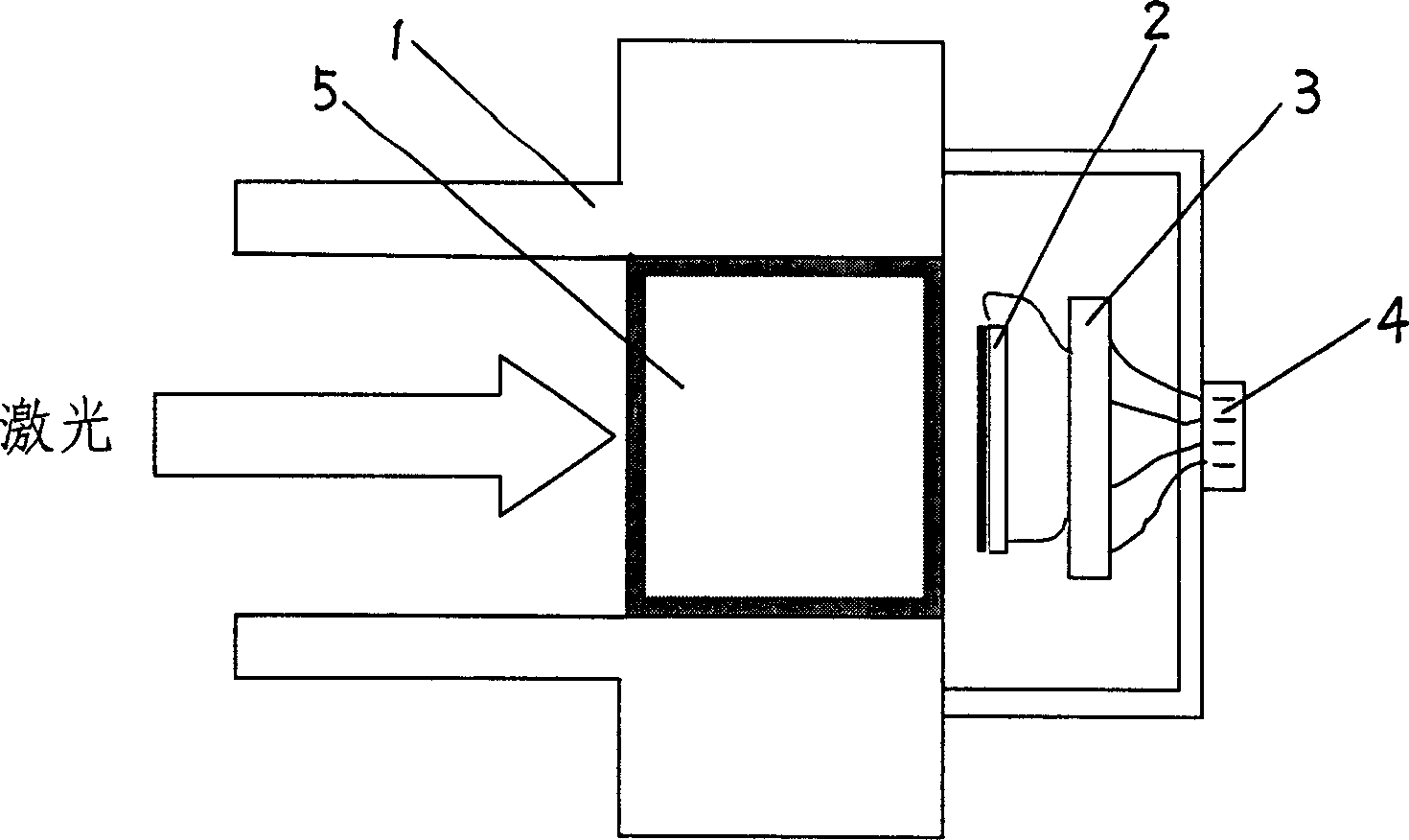
[0013] The laser energy meter structure of the present invention sees figure 1 , the laser energy meter has a tubular metal housing 1, in the rear part of the housing 1, a detector 2, an amplifier 3 and a signal output unit 4 are installed in sequence, and, in the front part of the housing 1 (referring to the detector 2) at an appropriate distance, a ceramic hollow cavity 5 is installed.

[0014] The ceramic hollow cavity 5 is a closed hollow cylinder, the axial direction of the cylinder is parallel to the direction in which the laser enters the casing, that is, the front surface of the ceramic hollow cavity 5 receives the laser light entering from the outside of the casing 1; and the ceramic hollow cavity 5. The side of the cylinder is closely connected with the inner wall of the metal shell 1.

[0015] In the present invention, the detector 2 uses a lead zircon...


PUM


Abstract

In a tubular metal shell successively are mounted detector, amplifier electrically-connected with said detector and signal processing unit, and between the laser incident hole of external shell and detector a ceramic hollow cavity is set, said ceramic hollow cavity is a closed hollow column body, and the axial direction of said column body is parallel to the direction of laser coming into the shell body. The invented laser energy meter can be used for measuring laser with high energy density.

Description

Technical field: [0001] The invention belongs to the field of laser detection, and in particular relates to a laser energy detector. Background technique: [0002] In the laser detection process, the detection of laser energy is a very important part. Existing laser energy meters, more advanced ones use pyroelectric devices as thermal detectors, which have higher response speed and sensitivity than ordinary thermal detectors, and only respond to alternating temperature signals, so they are very It is suitable as a device for detecting pulsed laser radiation energy. When the laser pulse width is less than a certain value (usually hundreds of microseconds), its output signal is proportional to the incident laser energy. However, the existing laser energy meter can only measure the laser energy below a hundred joules. When the laser energy is higher than the laser energy, the detector will be damaged; in order to adapt to the measurement of high energy density laser, the exis...

Claims


Application Information

Patent Timeline
Patent Type & Authority Applications(China)
IPC IPC(8): G01J1/42
Inventor 孙之旭杨在富马冲钱焕文杨景庚王嘉睿马萍
Owner NAT INST OF METROLOGY CHINA
Why Eureka
Try Eureka