Hydraulic fast-oscillating valve

A hydraulic and valve body technology, which is applied in the field of hydraulic valves, can solve problems such as inability to lay horizontally, use restrictions, etc., and achieve the effect of low energy consumption and high production

Inactive Publication Date: 2006-03-08
刘瑞祥
View PDF0 Cites 9 Cited by
  • Summary
  • Abstract
  • Description
  • Claims
  • Application Information

AI Technical Summary

Problems solved by technology

The Φ500 valve is already more than 3 meters high and can only be placed vertically instead of horizontally, which brings restrictions to the use

Method used


Image

  • Hydraulic fast-oscillating valve

Examples


Embodiment Construction

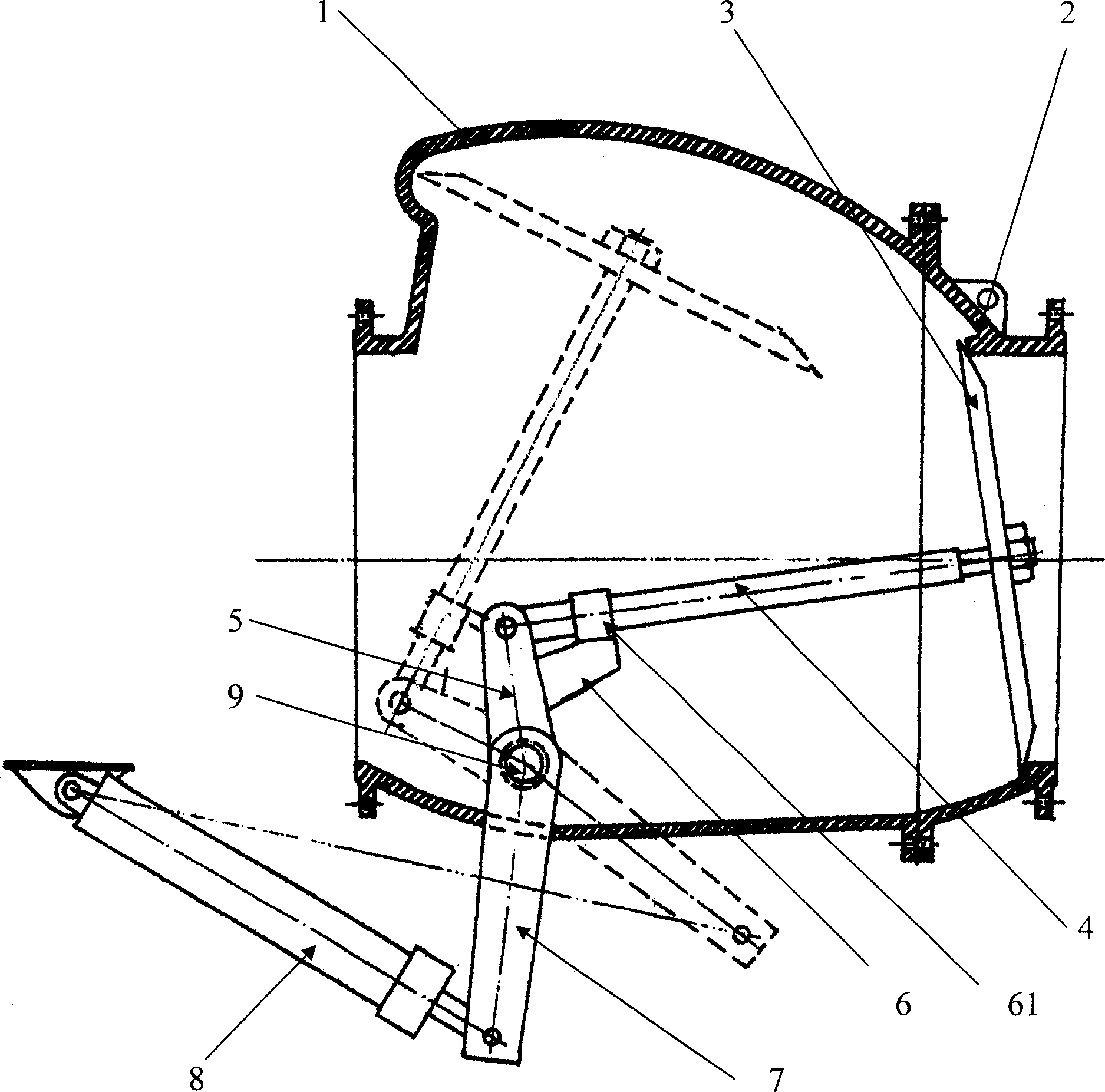
[0007] Such as figure 1 As shown, the hydraulic quick-swing valve of the present invention comprises a tubular valve body 1, which is rotatably provided with a rotating shaft 9 that is airtight with the valve body through the valve body 1 on one side of the valve body 1, and the axis of the valve body 1 is in line with the The axes of the rotating shaft 9 are vertical; the two ends of the rotating shaft 9 extend out of the valve body 1 and the power arm 7 connected with the hydraulic cylinder 8 is installed; the crank 5 is fixed on the rotating shaft 9 in the valve body 1, and the The other end is provided with a connecting rod 4, and the other end of the connecting rod 4 is equipped with a circular valve plate 3, and a valve seat 2 suitable for the circular valve plate 3 is provided in the inlet end of the valve body 1 toward the valve plate 3 , there is enough space for the circular valve plate 3 to rotate along the rotating shaft 9 in the valve body 1; when the hydraulic cy...


PUM


Abstract

A hydraulic quick swing valve, which contains pipe shape valve body, rotation axle with air seal, power arm set on axle and connected with hydraulic cylinder, crank on rotation axle, linking lever on another end of crank, round valve board on end of linking lever, valve base matched with round valve board. Said invention utilizes lever principle making crank and linking lever rotating and swing to generate speed and pressure difference resulting quick rotating and swing to obtain high production and low energy consumption.

Description

technical field [0001] The invention relates to a hydraulic valve, in particular to a large diameter hydraulic valve Background technique [0002] At present, in the fertilizer and gas industry, hydraulic gate valves are commonly used valves. In fixed-layer intermittent gas production, the valves must be opened and closed frequently. With the continuous expansion of the gas furnace, the gas production is also increasing, and large-diameter valves are required. To meet the needs of the production process. However, the height-to-diameter ratio of common hydraulic valves is generally about 6 times. The Φ500 valve is already more than 3 meters high, and it can only be placed vertically, but cannot be placed horizontally, which brings restrictions to its use. Contents of the invention [0003] In order to overcome the above defects, the object of the present invention is to provide a hydraulic fast swing valve with simple structure and high swing speed. [0004] To achieve t...

Claims


Application Information

Patent Timeline
Patent Type & Authority Applications(China)
IPC IPC(8): F16K1/20F16K31/122
Inventor 刘瑞祥
Owner 刘瑞祥
Why Eureka
Try Eureka