Device for coupling two shafts having an axial offset

An axis and crankshaft technology, applied in the field of devices coupling a first shaft and a second shaft, can solve problems such as radial force, and achieve the effects of compensating for axis misalignment, small weight, and high damping ratio

Inactive Publication Date: 2006-03-15
LUK LAMELLEN & KUPPLUNGSBAU BETEILIGUNGS KG
View PDF0 Cites 9 Cited by
  • Summary
  • Abstract
  • Description
  • Claims
  • Application Information

AI Technical Summary

Problems solved by technology

Essentially the compensation of the tolerances can be achieved by the elasticity present in the system, but in this case radial forces can occur on the two shafts to be coupled

Method used


Image

  • Device for coupling two shafts having an axial offset
  • Device for coupling two shafts having an axial offset
  • Device for coupling two shafts having an axial offset

Examples


Embodiment Construction

[0036] Identical or functionally similar parts are provided with the same reference numerals in the following description of the figures.

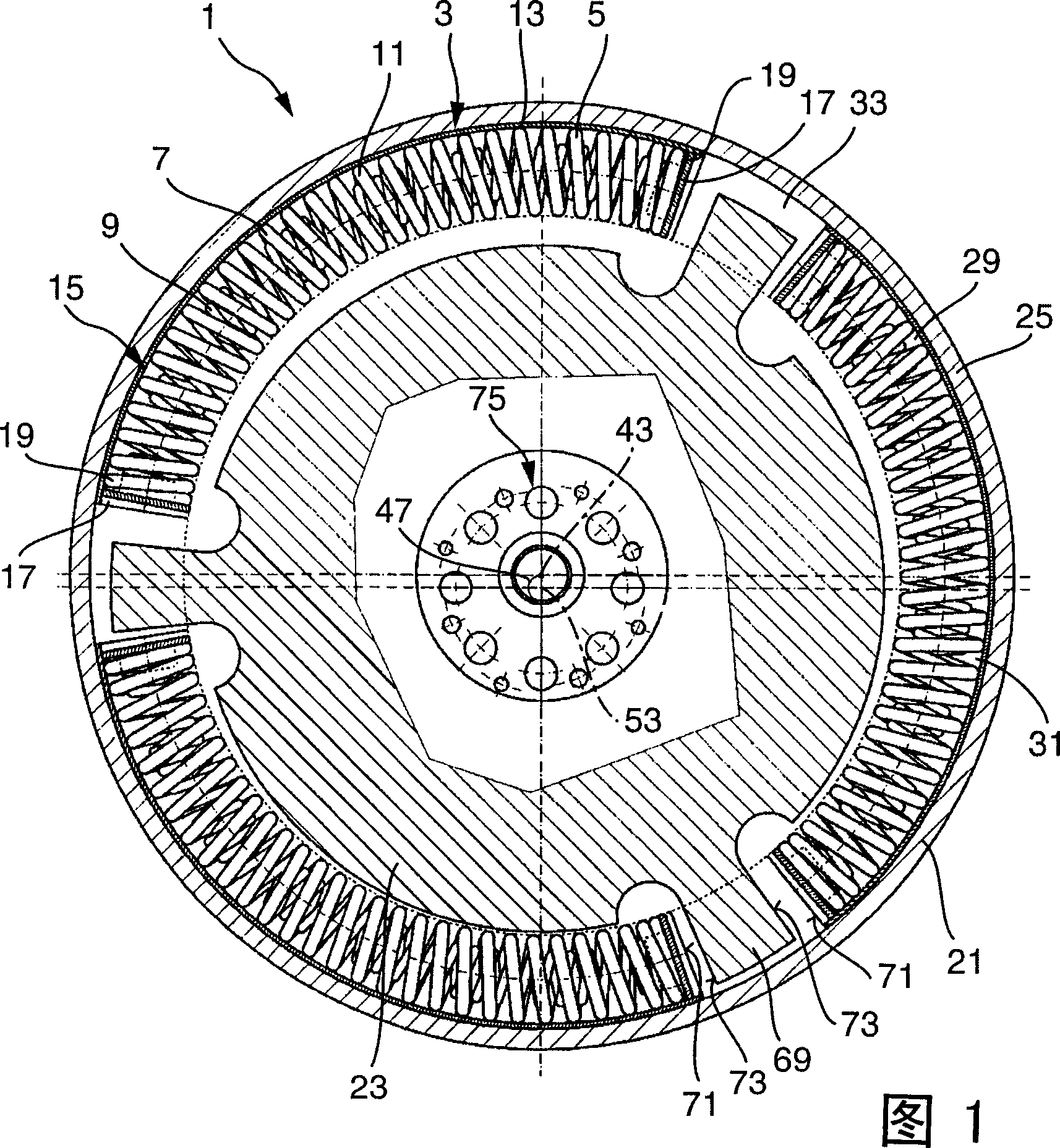
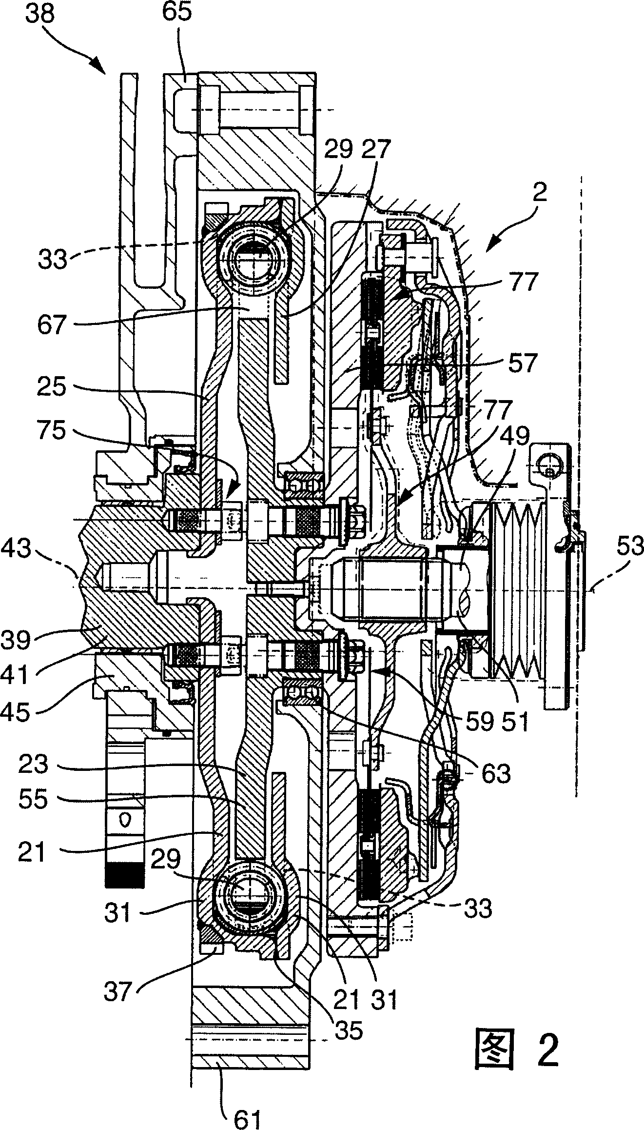
[0037]FIG. 1 shows a cross-sectional view of a device 1 for coupling two shafts with a torsional vibration damper 3 having a curved spring damper 5 . FIG. 2 shows a longitudinal section through the device 1 shown in FIG. 1 with a flanged dry clutch 2 . Dry clutches are well known and are used for coupling or decoupling two shafts, therefore, they are only described in this application to the extent necessary to understand the invention. 1 and 2 will be referred to simultaneously below.

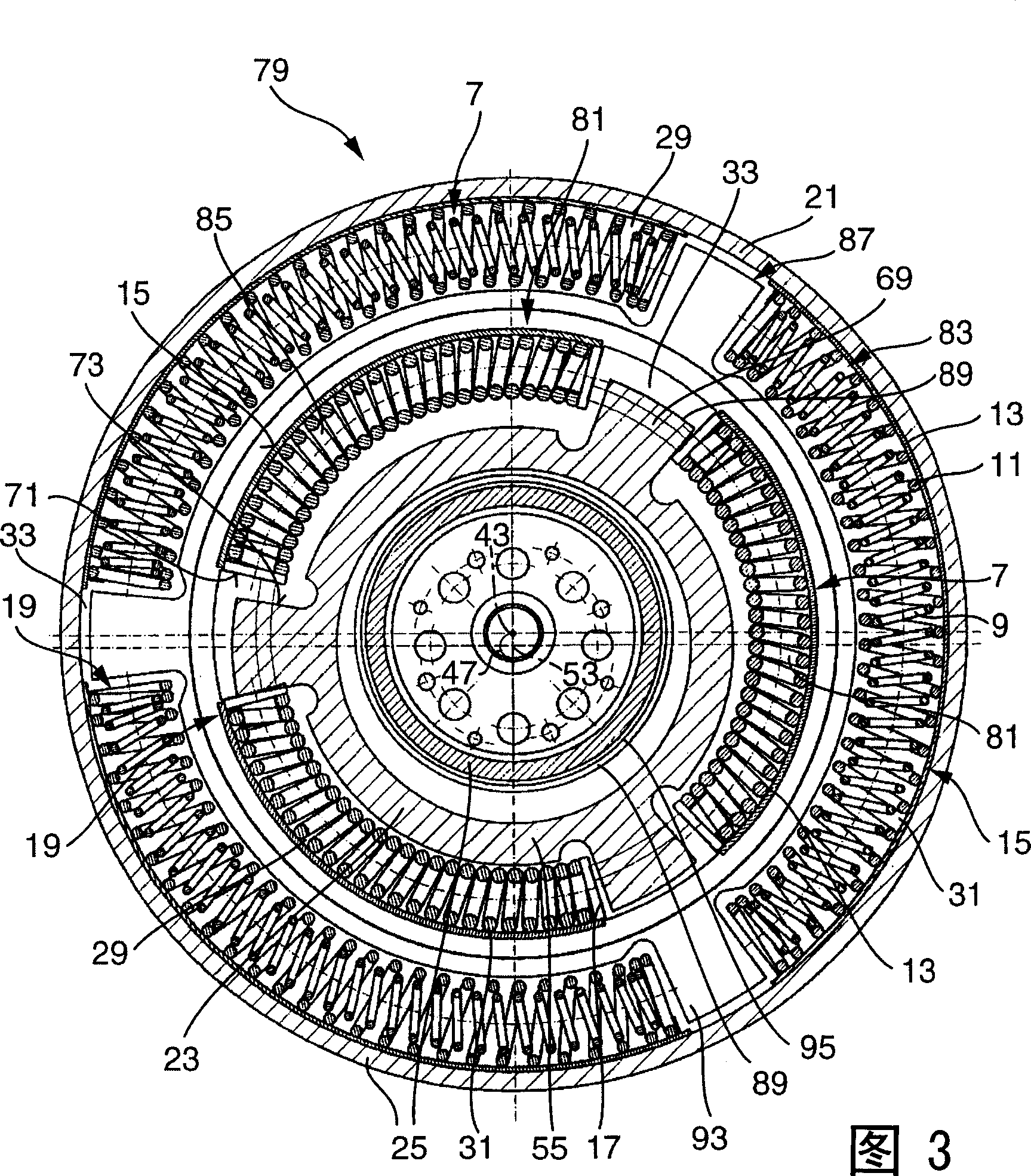
[0038] The arc spring damper 5 has three arc spring units 7 arranged on a radius. Each arc spring unit has an inner arc spring 9 and an outer arc spring 11 . Also can each only be provided with an arc spring when needed. In order to absorb the centrifugal force occurring on the outer arc spring 11, each arc spring unit 7 of the arc spring damper 5 of t...


PUM


Abstract

The invention relates to a device used to couple in a first axis and a second axis, wherein the axes have displaced axial lines and are arranged parallel in axial direction; the device is provided with at least one first rotating mass allocated for the first axis and at least one second rotating mass allocated for the second axis; in order to transmit torque, the device is also provided with at least one first stop surface coupled in the first axis and a second stop surface coupled in the second axis; moreover, the stop surfaces contact each other during transmitting torque; the first stop surface is fixed relative to a position in the radial direction of the first axis, while the second stop surface is fixed relative to a position in the radial direction of the second axis.

Description

technical field [0001] The invention relates to a device for coupling a first shaft and a second shaft. The two shafts have an axial offset and are arranged axially parallel to each other. Background technique [0002] Devices of the type described are known. This arrangement is preferably used in engines with variable compression ratio and / or variable piston displacement. The adjustment of the compression ratio in such engines can be achieved by means of an eccentric mounting of the crankshaft, whereby a misalignment occurs between the crankshaft and the output shaft which is normally coupled to the engine. Crankshaft bearings are known in which the axis of rotation of the crankshaft is displaced along a cylindrical enveloping surface and the axis of rotation of the output shaft extends concentrically to the center axis of the enveloping cylinder. A constant displacement of the crankshaft relative to the output shaft is thus obtained independently of the adjustment of th...

Claims


Application Information

Patent Timeline
Patent Type & Authority Applications(China)
IPC IPC(8): F16D3/06F16F15/10F16F15/121
CPCF16D2013/703F16D3/06F16D13/58F16D3/66F16D13/70F16F15/1343F16F15/13484
Inventor 菲利普·施韦德勒约翰·耶克尔
Owner LUK LAMELLEN & KUPPLUNGSBAU BETEILIGUNGS KG
Why Eureka
Try Eureka