
Catalyst flow meter

A catalyst and mass technology, applied in indirect mass flow meters, mass flow measurement devices, measuring flow/mass flow, etc., can solve problems such as expensive and complex systems

Inactive Publication Date: 2006-03-15
ボレアリステクノロジーオイ
View PDF1 Cites 1 Cited by
  • Summary
  • Abstract
  • Description
  • Claims
  • Application Information

AI Technical Summary

Problems solved by technology

[0020] However, this system is quite complex and expensive
Plus, it requires a lot of maintenance

Method used


Image

  • Catalyst flow meter
  • Catalyst flow meter
  • Catalyst flow meter

Examples


Embodiment Construction

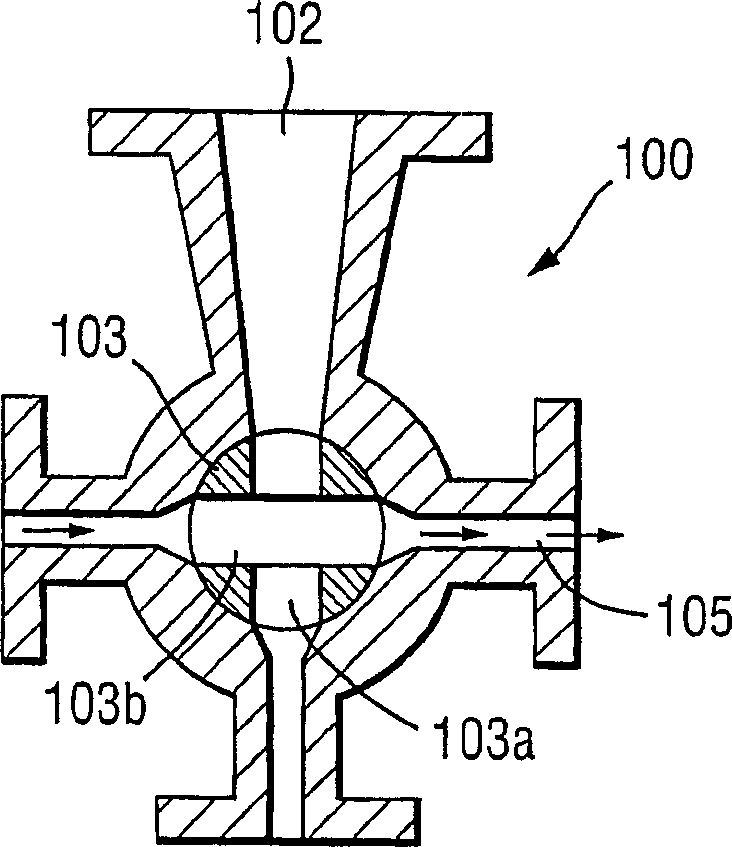
[0079] As mentioned above, figure 1A standard catalyst feeder 100 is shown for feeding a plug of catalyst to the reactor. The feeder 100 comprises a circular valve 103 comprising two disconnected channels 103a, 103b arranged perpendicular to each other. A valve 103 is provided at the connection between the catalyst canister and the channel 105 leading to the reactor. Valve 103 is rotated so that channel 103a is filled with catalyst. The valve is then turned 90° so that the catalyst can be flushed towards the reactor by the flow of diluent along channel 105 . Meanwhile, the second channel 103b is in line with the catalyst tank and is supplied with catalyst. In this way, a fixed amount of catalyst can be continuously supplied to the reactor.

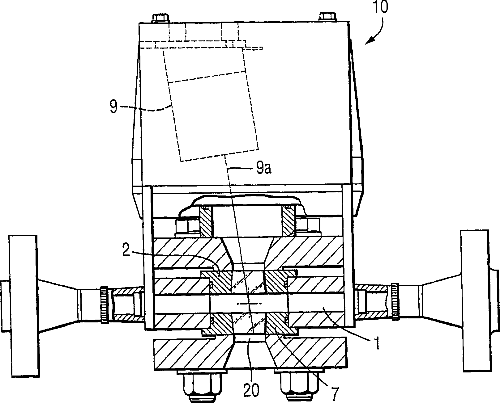
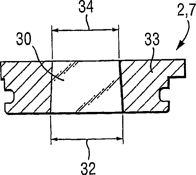
[0080] Light intensity detector 10 of the present invention (see figure 2 ) is arranged downstream of the feeder 100 along the channel 105. The device is based on a laser 9 which passes a beam 9 a through the sight glass 2 , the cat...


PUM


Abstract

An apparatus (10) for detecting the transmission of catalyst plugs through a conduit (105) leading to a, polymerisation reactor, comprising an optical radiation source (9) located outside the conduit which passes a light beam (9a) through the conduit along a light path and an optical radiation detector arranged to detect the light beam. When a catalyst plug passes through the conduit it blocks the light path and thus the light intensity recorded by the detector drops. In this way catalyst plugs can be detected. The apparatus can also be used to measure the mass of an object passing through a conduit by repeatedly detecting the speed of the material and the light intensity, multiplying the speed and intensity values to get a result curve and integrating this curve in order to obtain a value indicative of the mass of the material.

Description

technical field [0001] The present invention relates to devices for detecting the transport of material through pipelines. A preferred form of the invention relates to catalyst flow meters, particularly catalyst flow meters for use in polymerization plants. Background technique [0002] Polymers such as polyethylene are generally produced in a pressure reactor using a so-called slurry system. In the pressure reactor, polymer is continuously formed as liquid reactants circulate around the loop reactor. The finished polymer is formed as a solid suspended in a liquid. [0003] When polyethylene is produced in this way, high-purity ethylene is sent to a loop reactor along with a catalyst and some other materials. A low boiling hydrocarbon such as isobutane or liquid propane is used to dissolve the ethylene monomer and to suspend the catalyst and polymer particles within the reactor. This diluent does not participate in the actual polymerization reaction, so it is finally rec...

Claims


Application Information

Patent Timeline
IPC IPC(8): G01F1/74G01F1/86G01N21/55G01N21/59G01F1/00
CPCG01N21/59G01F1/00G01F1/86
Inventor 卡尔·尼尔森
Owner ボレアリステクノロジーオイ
Learn More