Method and device for recognizing leaks

A technology of internal leakage and gas leakage, applied in the direction of detecting the appearance of fluid at the leakage point, using liquid/vacuum degree for liquid tightness measurement, etc., can solve problems such as pipeline leakage detection

Inactive Publication Date: 2006-03-15
INFICON INC
View PDF3 Cites 6 Cited by
  • Summary
  • Abstract
  • Description
  • Claims
  • Application Information

AI Technical Summary

Problems solved by technology

Therefore, the pipeline cannot be leak detected during operation

Method used


Image

  • Method and device for recognizing leaks
  • Method and device for recognizing leaks
  • Method and device for recognizing leaks

Examples


Embodiment Construction

[0017] Various embodiments of the present invention will be described in detail below with reference to the accompanying drawings.

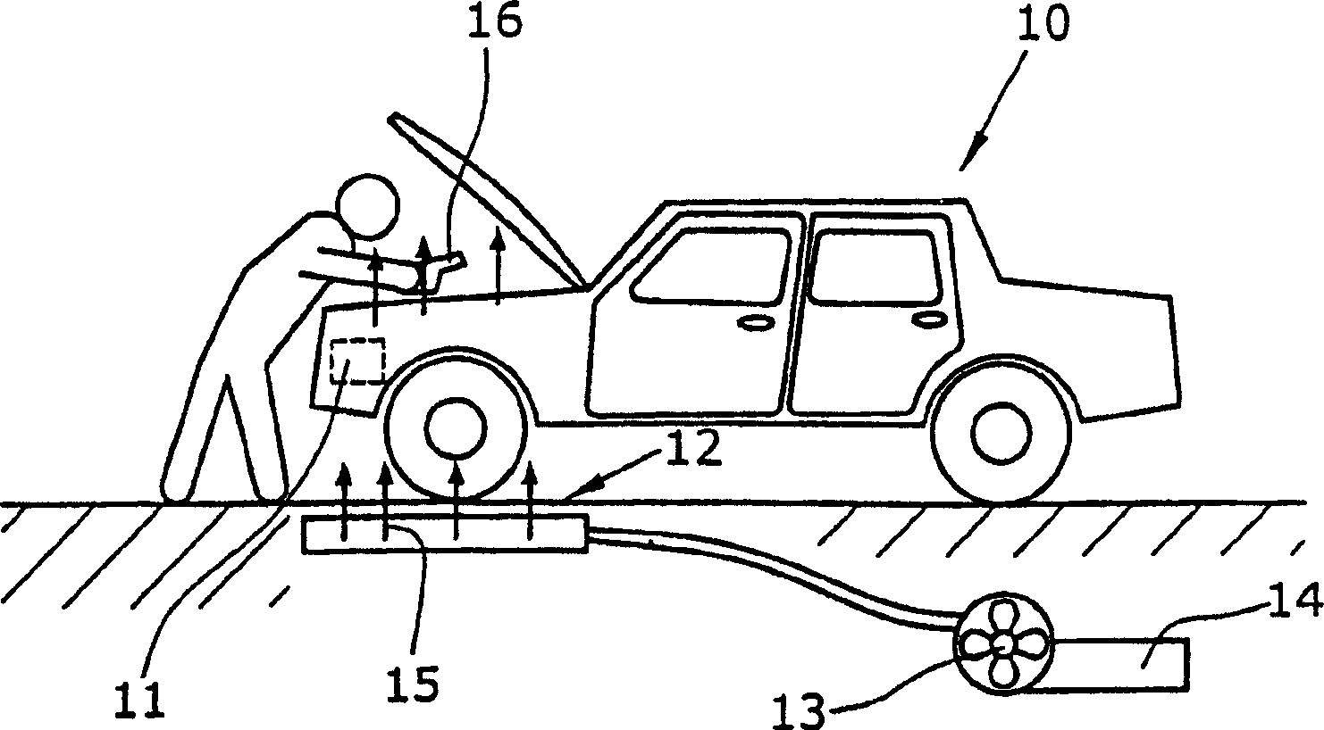
[0018] figure 1 The car is shown including its air conditioner assembly 11 in its engine compartment. The air conditioner has a coolant circuit that is required to be airtight. For gas leak detection, the air conditioner assembly 11 is arranged on a blowing device 12 connected to a fan 13 . The fan 13 draws in fresh air or another gas which does not contain the leakage gas to be detected via the inlet 14 . Fresh air contains concentrations of gases that can be used as leak gases (eg argon, carbon dioxide, helium). A gas flow 15 rises from said blowing means 12 and flows through the assembly 11 . Thereby, a defined environment is created in which leaking gas can be detected, ie the location of the detected gas, can be detected with the leak detection head 16 above the assembly 11 to detect the gas flow through the assembly 11 . The leak detec...


PUM


Abstract

In order to recognize or evaluate leaks in the operational area of a unit, the leak area that is to be tested is enclosed by a gas-tight housing (21). A sampling probe (16) is guided through the wall of the housing (21), enabling gas to be suctioned from the test area. Influences from the surrounding atmosphere are locked out of the test area in order to ensure that the measuring results are not distorted by gases, such as respiratory gases, which are contained in the surrounding atmosphere. The housing is entirely or partially pre-fitted in the operational area.

Description

technical field [0001] The present invention relates to a method and apparatus for detecting or identifying gas leaks using a leak detection device comprising a leak detection tip which senses leaking gas. technical background [0002] DE 101 18 085 A1 (Inficon GmbH) describes a leak detection device which enables the specific identification of different leaking gases and the respective determination of their quantity or concentration. For example, the refrigeration industry and the automotive industry can use this leak detection device to detect the device under test or assembly. The leak detection device includes a leak detection head that draws gas into the device. The test gas used to test the tightness of the device is often helium. It is also known to use gases already in equipment under test or assembly, such as SF6, as test gases, or to use halogen gases as test gases in the refrigeration industry. A frequently used test or leak gas is carbon dioxide. A particula...

Claims


Application Information

Patent Timeline
Patent Type & Authority Applications(China)
IPC IPC(8): G01M3/04G01M3/20G01M3/22
CPCG01M3/22G01M3/04G01M3/20
Inventor 维尔讷·格罗塞布莱托马斯·伯姆威利·舍尔
Owner INFICON INC
Why Eureka
Try Eureka