
Parallel type dust removing device of vacuum cleaner
A technology for dust removal devices and vacuum cleaners, which is applied in the direction of vacuum cleaners, suction filters, cyclone devices, etc., which can solve the problems of large volume of cyclone dust removal devices, troublesome use by users, and increased costs, so as to avoid dust raising, increase air volume, and air flow pressure loss small effect
- Summary
- Abstract
- Description
- Claims
- Application Information
AI Technical Summary
Problems solved by technology
Method used
Image

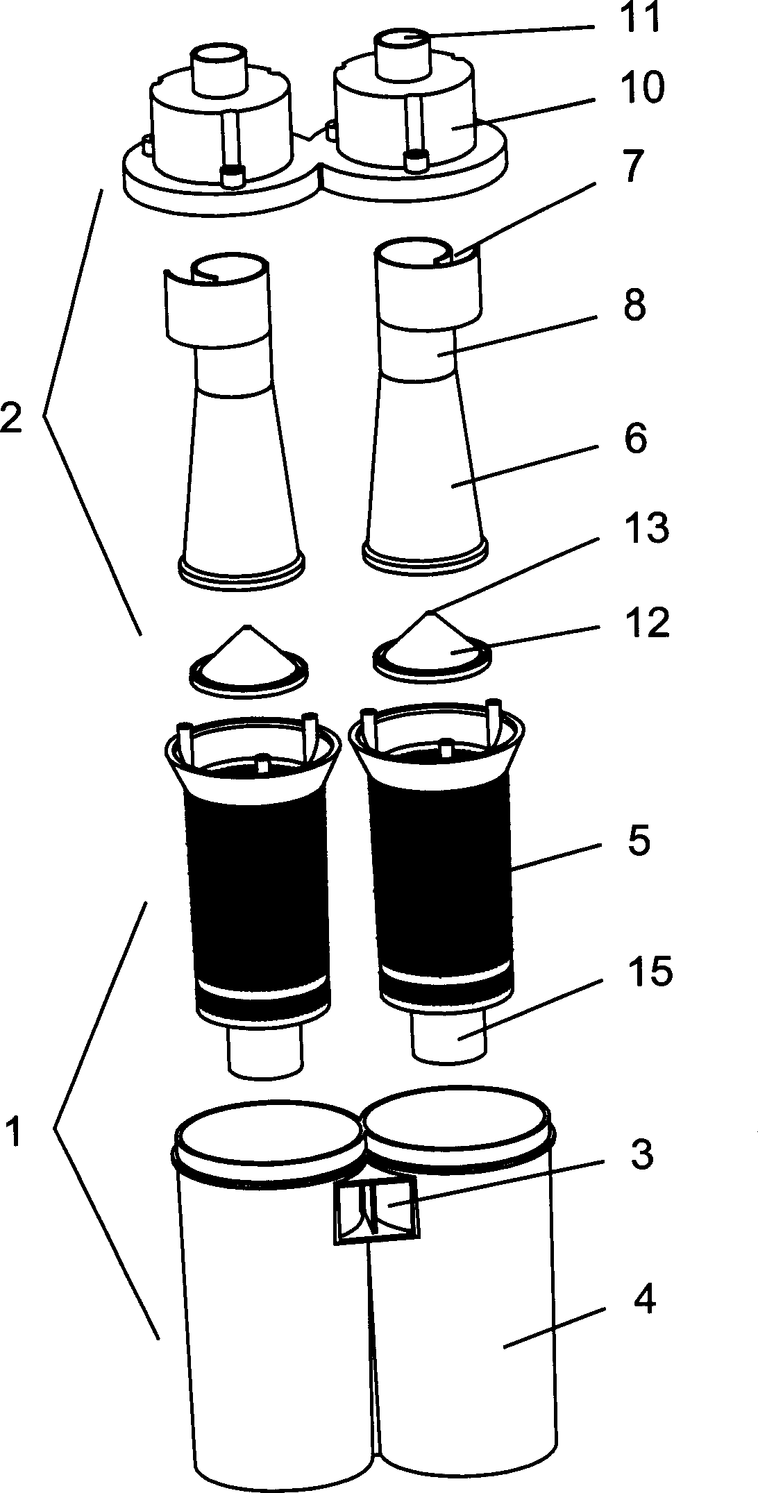

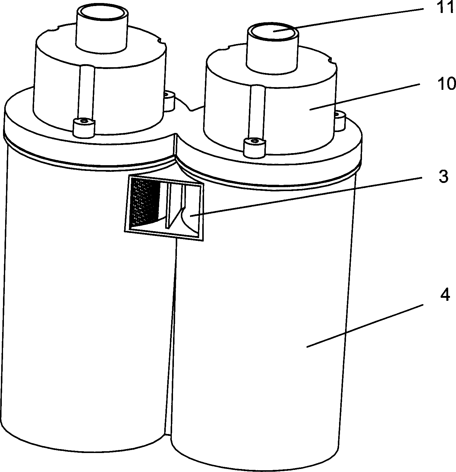
Examples
Embodiment
[0018] Example: such as figure 1 , figure 2 , image 3 As shown, a side-by-side vacuum cleaner dust removal device includes two upstream cyclone separators 1 arranged side by side. The upstream cyclone separator 1 includes a cylindrical dust cup 4 with a cyclone air inlet 3. Inside the cylindrical dust cup 4 A cylindrical filter cover 5 full of small holes is arranged coaxially, two cylindrical dust cups 4 are connected and fixed, and two cyclone air inlets 3 are adjacently arranged and communicated with the same air inlet pipe.
[0019] A downstream separator 2 is inserted in each of the upstream cyclone separators 1, and the downstream cyclone separator 2 includes a conical cylinder 6 and a cylindrical cylinder 8 with a cyclone air inlet 7, the cylindrical cylinder 8 Connected with the small end of the conical barrel 6, an air outlet pipe 9 is coaxially arranged inside the cylindrical barrel 8.
[0020] The conical shell 6 of the downstream cyclone separator 2 is inserte...
PUM
 Abstract
Description
Claims
Application Information