Moulding frame used for powder compression moulding machine

A technology of press forming and mold base, applied in the direction of presses, manufacturing tools, etc., to reduce the height, improve the degree of automation and production efficiency, and reduce the manufacturing cost

Inactive Publication Date: 2006-03-29
SOUTH CHINA UNIV OF TECH
View PDF1 Cites 4 Cited by
  • Summary
  • Abstract
  • Description
  • Claims
  • Application Information

AI Technical Summary

Problems solved by technology

[0003] The purpose of the present invention is to overcome the deficiencies of the prior art, through the improvement of the structure of the mold base, to provide a mold base for a powder compacting machine with a reasonable structure and easy operation, which can solve the problem of synchronous drive of the template; Die punches can be easily replaced when parts are removed

Method used


Image

  • Moulding frame used for powder compression moulding machine
  • Moulding frame used for powder compression moulding machine

Examples


Embodiment Construction

[0017] The present invention will be further described in detail with the following examples and drawings, but the embodiments of the present invention are not limited thereto.

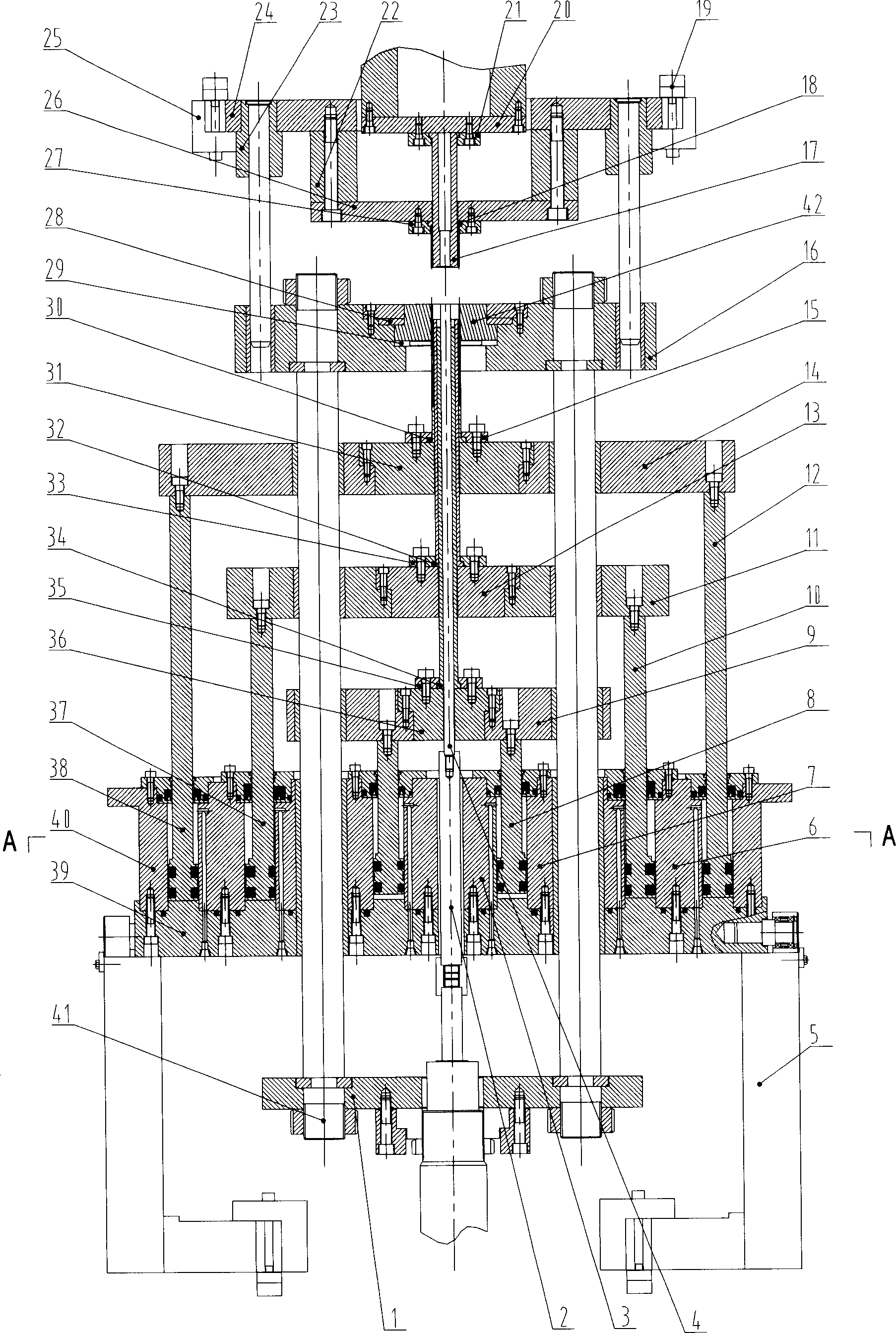
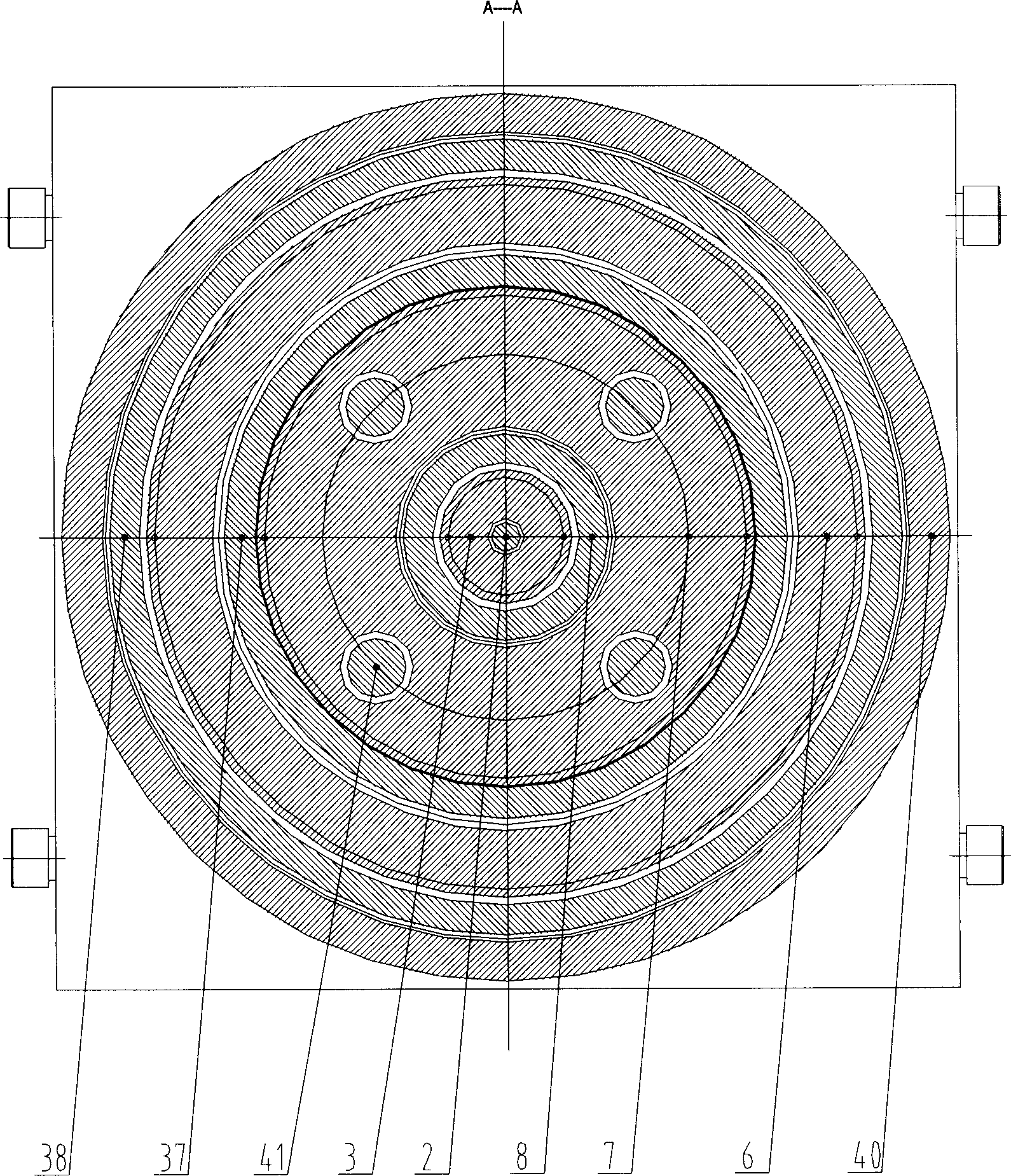
[0018] Such as figure 1 , figure 2 Shown, a structural form of the present invention, by figure 1 , figure 2 It can be seen that the three-layer template mold base for the powder compacting machine includes the following parts: connecting plate 1, connecting rod 2, inner wall of annular oil cylinder I 3, core rod 4, backing plate of mold base 5, outer wall of annular oil cylinder II 6, and annular oil cylinder I Outer wall 7, lower inner template ring driving rod 8, lower inner template 9, lower middle template ring driving rod 10, lower middle template 11, lower outer template ring driving rod 12, lower middle die punch connecting seat 13, lower outer template 14, Lower outer die stamping ring 15, female die seat 16, upper inner die punch 17, upper outer die punch 18, T-shaped block 19, upper inner die...


PUM


Abstract

A die holding frame for the die press of powder is composed of punch die and its jointer, the upper, external lower, medium lower and internal lower formworks, female and its holder, guide columns, three coaxial annular cylinders, and three annular drive rods associated with said three coaxial annular cylinders. Its advantages are synchronous drive to said formworks, and high quality of workpiece.

Description

Technical field [0001] The invention relates to powder metallurgy equipment, in particular to a mold base for a powder compacting machine. Background technique [0002] Powder metallurgy is the process and technology of manufacturing metal powder and using metal powder as the basic raw material to manufacture metal materials and special-shaped products. The mold base is an indispensable process equipment for manufacturing powder metallurgy products. In order to improve the performance of the mold base, a multi-layer template powder press molding mold base is disclosed in the Chinese invention patent No. 03139803.0, although this type of mold base is equipped with multiple table powder metallurgy parts of different types and shapes. However, this kind of mold base has the following problems: (1) Because of the use of integrated oil cylinders, each template needs to be driven by 4 oil cylinders. Therefore, during the movement of the template, the problem that t...

Claims


Application Information

Patent Timeline
Patent Type & Authority Applications(China)
IPC IPC(8): B22F3/03B30B15/02
Inventor 邵明宋雷李元元
Owner SOUTH CHINA UNIV OF TECH
Why Eureka
Try Eureka