Float load type oil recovering

An oil recovery and loading technology, which is used in floating buildings, water conservancy projects, and open-air water surface cleaning, etc., can solve problems such as the reduction of oil recovery rate, and achieve the effect of improving oil recovery rate and reducing height.

Inactive Publication Date: 2006-03-29
FUDO CONSTR
View PDF1 Cites 13 Cited by
  • Summary
  • Abstract
  • Description
  • Claims
  • Application Information

AI Technical Summary

Problems solved by technology

Therefore, there is a problem that the oil recovery rate decreases

Method used


Image

  • Float load type oil recovering
  • Float load type oil recovering
  • Float load type oil recovering

Examples


Embodiment Construction

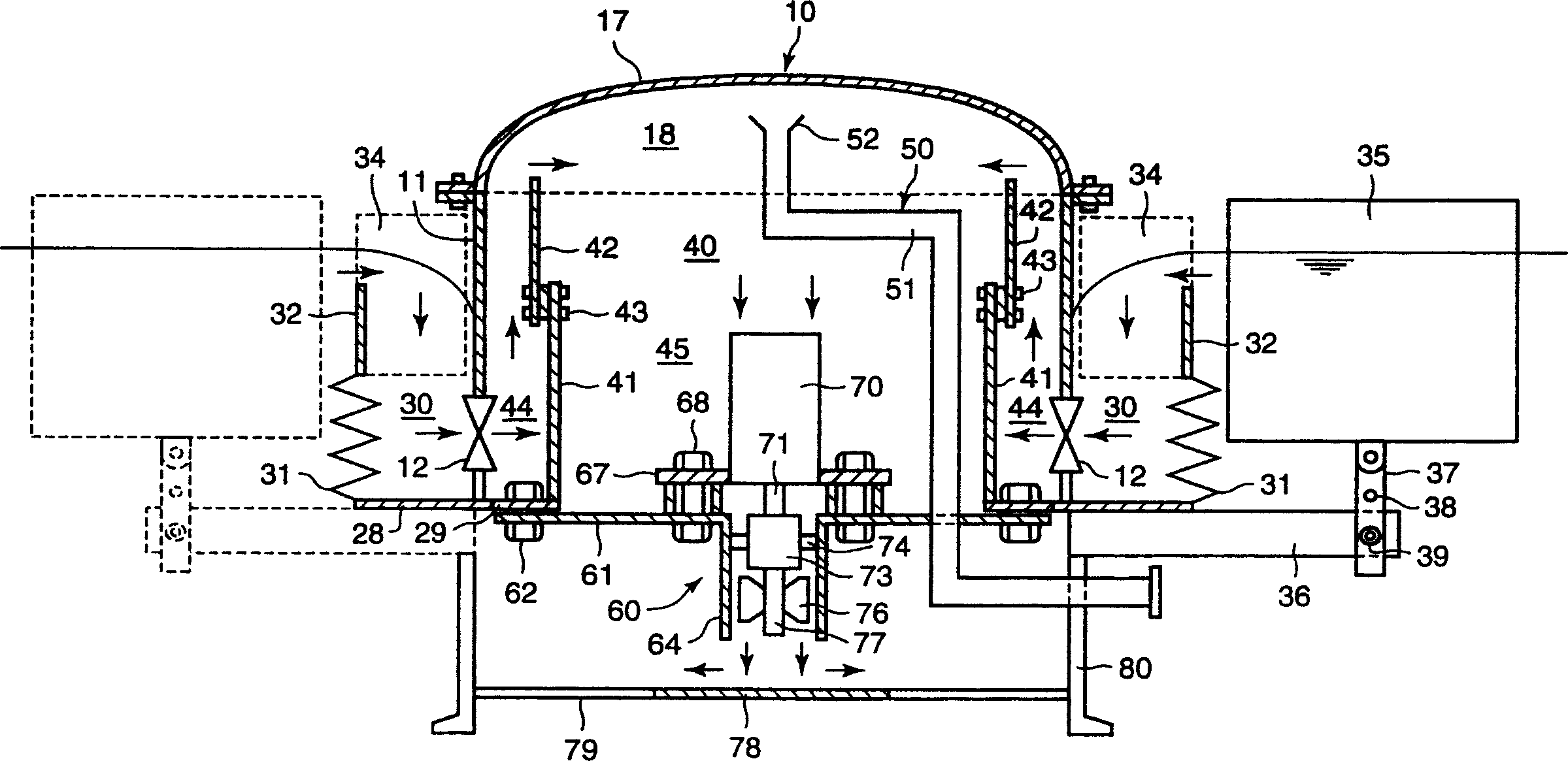
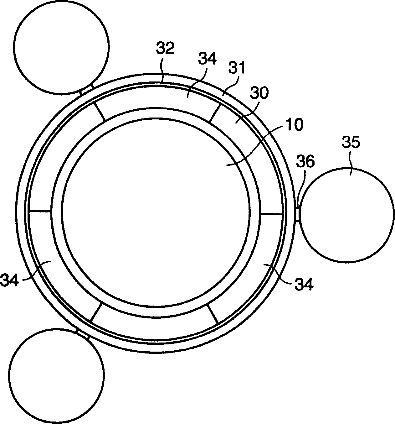
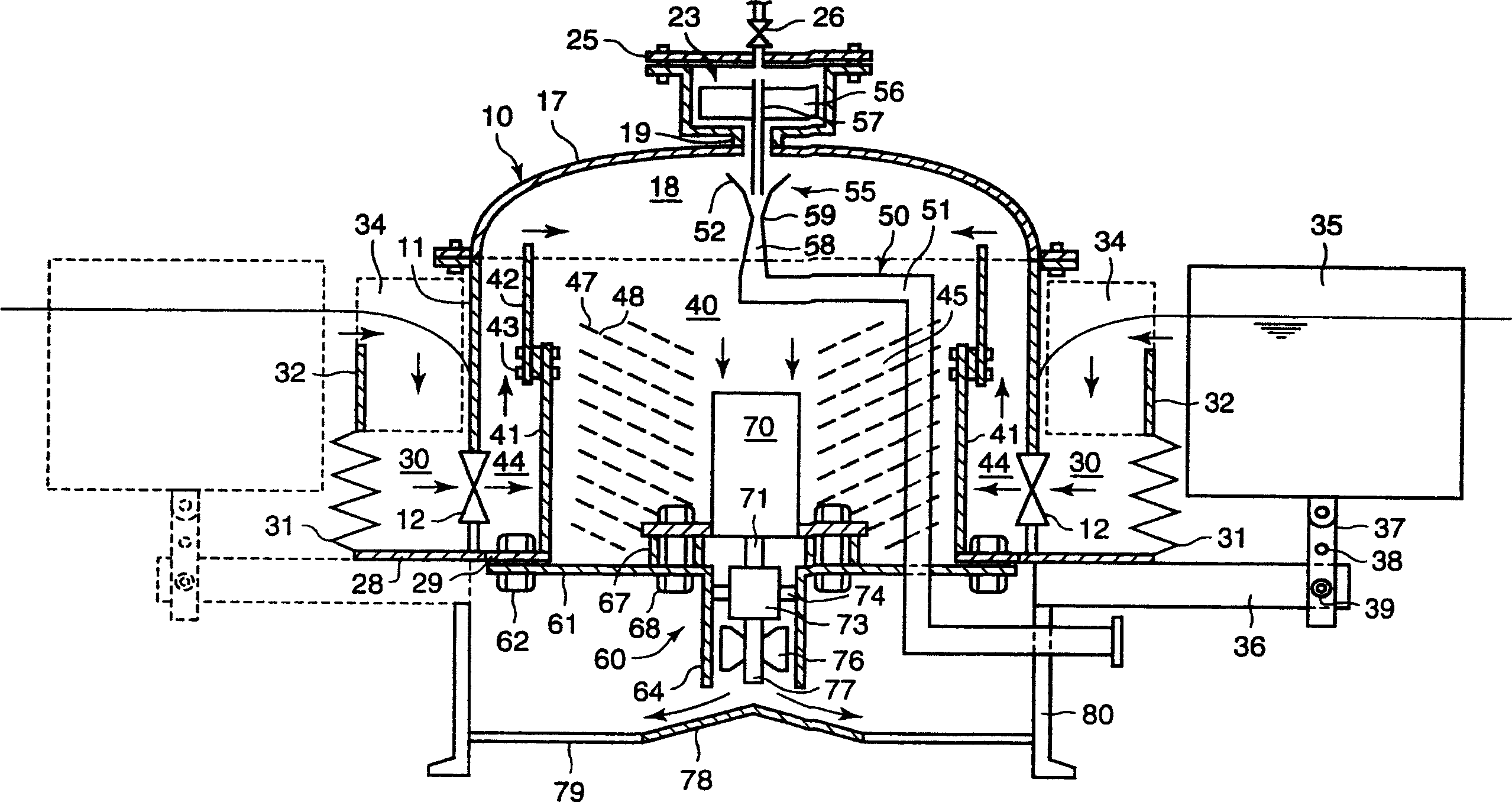
[0017] figure 1 and figure 2 represents the first form of the present invention, figure 1 To schematically represent a sectional view of an oil recovery unit, figure 2 for figure 1 Top view of the device shown. The oil recovery device is mainly composed of an oil-water separation chamber 10 , an oil-water inflow chamber 30 , an inner floating body 34 , an outer floating body 35 , an oil-water separation part 40 , an oil suction device 50 and a forced drainage device 60 .

[0018] The oil-water separation chamber 10 includes a cylindrical separation chamber main body 11 and a dome-shaped cover 17 attached to the top of the separation chamber main body 11 . Near the bottom of the main body 11 , a plurality of oil-water inlets 12 are provided at intervals along the circumferential direction. The oil-water inflow port 12 is located under the water surface to form a submerged weir. An oil reservoir 18 is formed inside the cover 17 . An annular bottom plate 28 is installed ...


PUM


Abstract

To provide a float-mounted type oil recovering apparatus enabling the recovery of even oil with a small particle size, and the improvement of the oil recovery rate. The float-mounted type oil recovering apparatus is provided with an oily water separating chamber having a cylindrical body 11 with a plurality of oily water inflow mouths under the water line, bellows arranged outside the oily water separating chamber body, an inflow gate attached to the top of the bellows, an oily water inflow chamber formed among the oily water separating chamber body and the bellows, and the inflow gate, a plurality of inner floats attached to the inflow gate, a plurality of outer floats attached to the outside of the oily water inflow chamber, an oil absorbing pipe extending from an oil basin to the outside of the oily water separating chamber, and a forced draining device provided on the bottom of the oily water separating chamber. The inside of the oily water separating chamber body is divided by a cylindrical partitioning wall, by which a coarse grain separating chamber is formed between the inner peripheral surface of the oily water separating chamber and the outer peripheral surface of the partitioning wall, and a fine grain separating chamber is formed inside the partitioning wall.

Description

technical field [0001] The present invention relates to a floating body loading type oil recovery device, in particular to a floating body loading type oil recovery device for recovering oil at recovery sites such as seas, lakes, swamps, and rivers. Background technique [0002] As a float-mounted oil recovery device, a float-mounted vortex type oil recovery device is known. The oil recovery device includes a swirl chamber and a water guide chamber for sending oil and water to the swirl chamber. Outer floating bodies are arranged outside the water guiding chamber, inner floating bodies are respectively fixed inside the water guiding chamber, and a forced drain is arranged at the bottom of the swirl chamber (for example, refer to Patent Document 1). The water is discharged from the bottom of the swirl chamber through the forced drainer, so that the oil and water flow from the water guiding chamber through the inlet of the swirl chamber and flow into the interior of the swirl...

Claims


Application Information

Patent Timeline
Patent Type & Authority Applications(China)
IPC IPC(8): E02B15/04B63B35/44
CPCY02A20/204
Inventor 宫田康弘
Owner FUDO CONSTR
Why Eureka
Try Eureka