Intermediate frequency heating pipe plastic liner device

A heating device and steel pipe technology, which is applied in the direction of tubular articles, other household appliances, household appliances, etc., can solve the problems of low production efficiency, complex structure, and large equipment volume, and achieve high production efficiency, simplify the device structure, and reduce the size of the device. volume effect

Active Publication Date: 2006-04-05
ZHEJIANG KINGLAND PIPELINE & TECH CO LTD
0 Cites 11 Cited by

AI-Extracted Technical Summary

Problems solved by technology

The disadvantages of this processing device are that the structure is more co...

Abstract

This invention relates to one medium heating steel tube plastic device, which comprises the following parts: sealing head on both ends of steel tube; charging structure; steel tube sending machine and heating device, wherein, the heating device adopts medium frequency induce heating coil; the said sealing head device is one pair of self-locking block with one end in plat cover shape and with hole in center and with self-sealed rap0id joint and with other end as column plug opened with semi-round card groove with two block ends connected through spring. This invention alters traditional large fuel strove heating device and complex gas cylinder sealed head device.

Application Domain

Technology Topic

Image

  • Intermediate frequency heating pipe plastic liner device
  • Intermediate frequency heating pipe plastic liner device
  • Intermediate frequency heating pipe plastic liner device

Examples

  • Experimental program(1)

Example Embodiment

[0009] In the following, the present invention will be further described with embodiments in conjunction with the accompanying drawings.
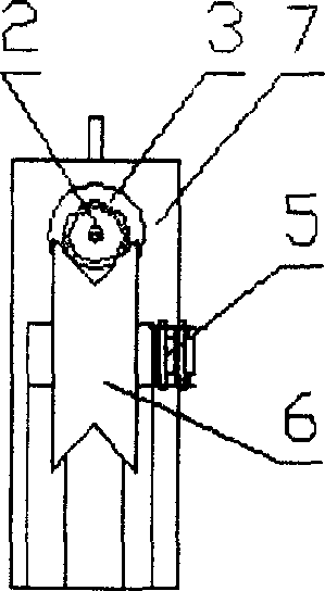
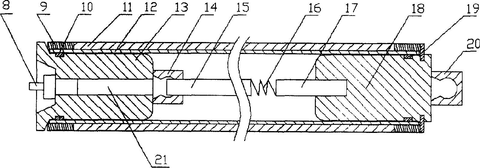
[0010] A pair of self-locking sealing plugs 13, 18 are made of steel. One end of the plug 13 is in the shape of a flat-top bottle stopper. The outer diameter of the stopper body is slightly smaller than the inner diameter of the lined plastic pipe 12. The diameter of the flat cover of the stopper body is equal to the outer diameter of the steel pipe 11, and an axial through hole 21 is opened in the stopper body. The outer port of the axial through hole 21 is equipped with a self-closing quick connector 8 for inflation, and a pull ring 14 is provided on the inner end of the plug; the other end plug 18 is a straight plunger with a diameter slightly smaller than the inner diameter of the lined plastic pipe, outside the straight plunger The end is provided with a ring groove that matches with the semicircular snap ring 19. A pull ring 20 is provided on the outer end of the straight plunger, and a tension spring connecting rod 17 made of steel is provided in the center of the inner end surface. One end of the tension spring 16 is opposite to the connecting rod 17. The other end is connected with a hook connecting rod 15 with a hook at the front end. The sealing ring 10 is installed in a ring groove opened where the plug bodies of the plugs 13 and 18 and the two exposed sections of the lined plastic pipe 12 are mated. The processed steel pipe 2 is composed of a steel pipe 11 and a plastic lined pipe 12 inserted close to the inner wall of the steel pipe 11. The plastic lined pipe is slightly longer than the steel pipe 11 and is on the pipe section of the lined plastic pipe 12 that extends outside the two ends of the steel pipe 11 Put on the anti-induction copper sleeve 9. As attached figure 2 When starting processing, first insert the plug 18 that connects the connecting rod 17, the tension spring 16, and the hook connecting rod 15 from right to left into the lined plastic pipe of the processed steel pipe 2 until the hook hook at the front end of the hook connecting rod 15 Hold the pull ring 14 on the inner end surface of the plug 13 and use a tool to hook the pull ring 20 on the outer end surface of the plug 18 and pull it outward. Insert a semicircular snap ring 19 inside, so the plugs 13, 18 are connected to the tension spring 16 to block the two ports of the processed steel pipe 2. The sealing ring 10 on the plugs 13, 18 is just in the anti-induction copper sleeve In the two exposed sections of the lined plastic pipe 12 with a lower temperature below 9; at this time, the compressed air is filled into the lined plastic pipe from the air source 1 through the self-closing quick connector 8 for inflation on the plug 13 at the inflation pressure of 0.2~ 0.4MPa; the inflated steel pipe to be processed is placed on a single-track roller table consisting of a number of V-groove rollers 6 and its transmission shaft 5, and transmission chain 4, and passes through the intermediate frequency induction heating coil placed in the middle of the track at an appropriate speed 3. Complete the heating process; then cool by the spray device 7 on the roller table; remove the compressed air in the pipe by squeezing the pressure relief thimble of the self-closing quick connector 8 for inflation; remove the plugs 13, 18 and anti-aircraft pipes at both ends of the processed steel pipe Induction copper sleeve 9; Finally, cut off the plastic pipe section whose inner plastic pipe 12 is longer than the steel pipe part to obtain the plastic-lined composite steel pipe product.

PUM

no PUM

Description & Claims & Application Information

We can also present the details of the Description, Claims and Application information to help users get a comprehensive understanding of the technical details of the patent, such as background art, summary of invention, brief description of drawings, description of embodiments, and other original content. On the other hand, users can also determine the specific scope of protection of the technology through the list of claims; as well as understand the changes in the life cycle of the technology with the presentation of the patent timeline. Login to view more.

Similar technology patents

Classification and recommendation of technical efficacy words

  • Simple device structure
  • Small device size

MEMS (Micro Electro Mechanical System) microphone and pressure integration sensor, and manufacturing method thereof

ActiveCN102158787AImprove standardization and unificationSmall device sizeSemiconductor electrostatic transducersElectrostatic transducer microphonesSignal-to-noise ratio (imaging)Mems microphone
Owner:MEMSEN ELECTRONICS

Multi-stage interferometer circuit with waveform shaping function

ActiveUS20180034555A1Device sizeSmall device sizeOptical multiplexElectromagnetic receiversOptical couplerPhysics
Owner:NIPPON TELEGRAPH & TELEPHONE CORP

Optical logic gate based on double parallel microring resonators

InactiveCN102062988ASmall device sizeReduce power consumptionLogic circuits using opto-electronic devicesInstrumentsPhysicsOptical logic gates
Owner:INST OF SEMICONDUCTORS - CHINESE ACAD OF SCI

Replacing device for battery boxes of electric vehicle

Owner:BEIJING STATE GRID PURUI EXTRA HIGH VOLTAGE POWER TRANSMISSION TECH CO LTD +1

Rotary-type compound nanometer power generator

InactiveCN105680716AImprove energy conversion efficiency and output currentSmall device sizeFriction generatorsSynchronous machines with stationary armatures and rotating magnetsStatorMagnet
Owner:BEIJING INST OF NANOENERGY & NANOSYST
Why Eureka
Try Eureka