Instrument for detecting wall thickness of glass tube

A detector and glass tube technology, applied in the field of glass tube wall thickness detector, can solve unscientific, time-consuming and labor-intensive problems, achieve standard quality, improve sorting speed, and reduce labor intensity of workers

Inactive Publication Date: 2006-04-05
宋才秀 +1
View PDF0 Cites 7 Cited by
  • Summary
  • Abstract
  • Description
  • Claims
  • Application Information

AI Technical Summary

Problems solved by technology

Glass tube manufacturers have done a good job of controlling and sorting the outer diameter of glass tubes through laser caliper gauges, etc., but because there is no online testing equipment for wall thickness, manufacturers still stop at manual measurement of (cut) glass tube ends In terms of status, it is neither scientific nor time-consuming

Method used


Image

  • Instrument for detecting wall thickness of glass tube
  • Instrument for detecting wall thickness of glass tube
  • Instrument for detecting wall thickness of glass tube

Examples


Embodiment Construction

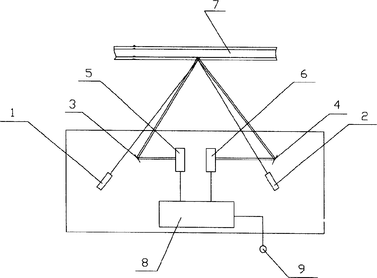
[0021] The specific implementation manner of the present invention will be described below in conjunction with the accompanying drawings.

[0022] Optical principle of the present invention:

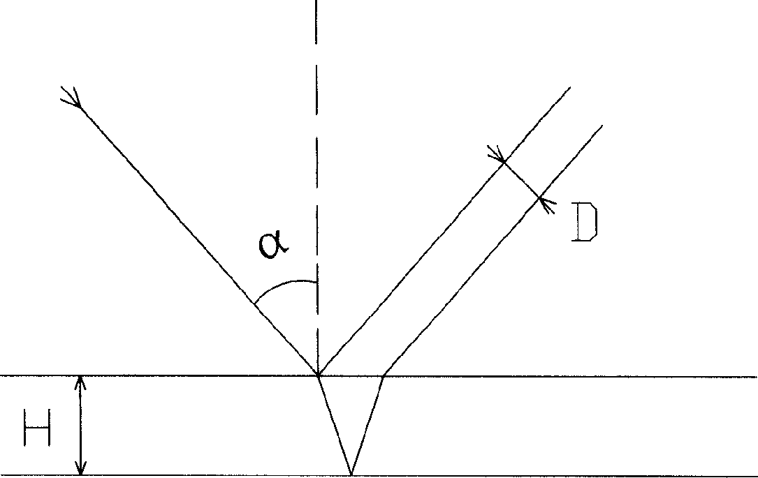
[0023] Such as figure 1 As shown, the present invention utilizes the good directivity of the laser, uses a semiconductor laser to shoot at a certain angle to the online glass tube and is perpendicular to its busbar, and calculates the wall thickness by measuring the displacement of the reflected light from the inner and outer busbars of the glass tube. Contact, high-speed measurement. The measurement formula is as follows:

[0024] H=D*(n 2 -sin 2 a) 1 / 2 / sin2α

[0025] In the formula: H is the wall thickness of the glass tube; D is the displacement of the reflected light;

[0026] α is the laser incident angle; n is the glass refractive index.

[0027] After the instrument is installed, the α angle is a fixed value, and it can be seen that the wall thickness H is proportional to...


PUM


Abstract

The invention discloses a glass pipe thickness detector which comprises a probe, a host machine, an output device and an interface, wherein the probe comprises a catalytic combustion detector and a semiconductor laser. It uses double light beam measurement; the driving circuit of the catalytic combustion detector includes a oscillation circuit, a frequency divider and a converter.

Description

technical field [0001] The invention relates to a testing instrument, in particular to a glass tube wall thickness testing instrument. Background technique [0002] Glass tubes are mainly used in the production of medicinal glass bottles. The outer diameter and wall thickness of glass tubes are the outer diameter and wall thickness of medicinal glass bottles. The country has standard requirements for medicinal glass bottles. Therefore, the outer diameter and wall thickness are important parameters of the glass tube. Glass tube manufacturers have done a good job of controlling and sorting the outer diameter of glass tubes through laser caliper gauges, etc., but because there is no online testing equipment for wall thickness, manufacturers still stop at manual measurement of (cut) glass tube ends In terms of status, it is neither scientific nor time-consuming. Contents of the invention [0003] The purpose of the present invention is to overcome the deficiencies of the abo...

Claims


Application Information

Patent Timeline
Patent Type & Authority Applications(China)
IPC IPC(8): G01B11/06
Inventor 宋才秀任月吉
Owner 宋才秀
Why Eureka
Try Eureka