Method for making light guide plate and side light type backlight assembly

A technology of backlight components and light guide plates, applied in optics, diffusion elements, nonlinear optics, etc., can solve the deviation of light distribution, cannot accurately control the density of light guide plates, and cannot effectively improve the reproduction of mold making sexual issues

Inactive Publication Date: 2006-04-05
NANO PRECISION
View PDF0 Cites 6 Cited by
  • Summary
  • Abstract
  • Description
  • Claims
  • Application Information

AI Technical Summary

Problems solved by technology

[0006] However, in the known light guide plate manufacturing technology, since the mold for making the light guide plate is processed by sandblasting or etching to form a pattern with a fog surface or a dotted surface structure, the reproducibility of sandblasting and etching is not good, so it cannot be effective. Improve the reproducibility of mold making, which often causes the deviation of light distribution during mold making; in addition, in terms of controlling the density distribution of the light guide plate pattern, if you want to use the sandblasting surface to adjust the light guide plate pattern density with different roughness distribution The dense distribution, and then adjust the uniformity of the backlight assembly. Unfortunately, the current sandblasting technology cannot accurately control the density of processing points in different areas on the light guide plate. However, if only the entire surface can be made with the same roughness If the surface is sandblasted and matte, the uniformity of the light emitted by the backlight components is not easy to adjust, which is the bottleneck faced by the production of light guide plates today.

Method used


Image

  • Method for making light guide plate and side light type backlight assembly
  • Method for making light guide plate and side light type backlight assembly
  • Method for making light guide plate and side light type backlight assembly

Examples


Embodiment Construction

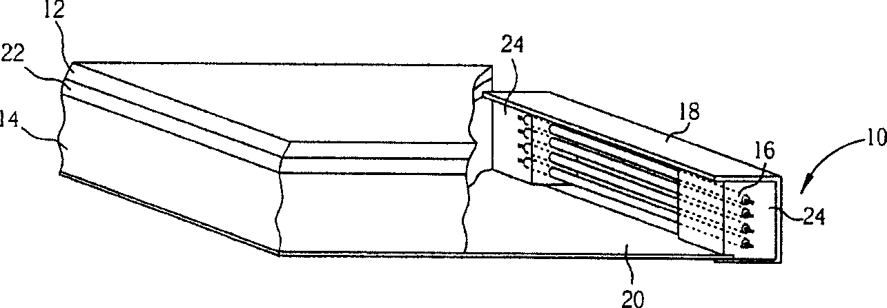
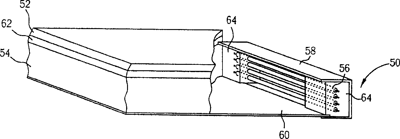
[0024] refer to image 3 , the edge-lit backlight assembly 50 of the present invention comprises: a light guide plate 54 arranged below the display panel 52; a light source 56 arranged on one side of the light guide plate 54, which can be a plurality of cold cathode fluorescent tubes; A lampshade 58 on the outside of the light source 56; a reflection plate 60 located below the light guide plate 54; an optical material layer 62 located between the light guide plate 54 and the display panel 52; and two lamp tube fixing members 64, the two The lamp tube fixture 64 is installed on both sides of the light source 56 to fix the light source 56; wherein, the lampshade 58 and the reflector 60 are used to reflect the light generated by the light source 56 into the light guide plate 54, and the light guide plate 54 is used to The light from the light source 56 scatters to the optical material layer 62 , thereby providing the display panel 52 with uniform and higher brightness at the fron...


PUM


Abstract

The invention relates to a method for making light guiding plate and a side light type negative phototropic component. The method comprises: using the laser to form an uneven surface on a mold and using the mold to make the light guiding plate so as to form the uneven surface which is formed by the micro mirror plate structure on the light guiding plate.

Description

technical field [0001] The invention provides a method for manufacturing a light guide plate and the light guide plate, especially a method for manufacturing a light guide plate processed by laser and the light guide plate. Background technique [0002] Since the liquid crystal itself does not emit light, the backlight assembly is a key component of a liquid crystal display (LCD) panel. Its main function is to supply a light source with sufficient brightness and uniform distribution, so that the LCD panel can display images normally. As LCD panels have been widely used in many electronic products with growth potential, such as monitors, notebook computers, digital cameras, projectors, etc., the demand for backlight components and related components is also growing continuously. [0003] Generally speaking, the backlight assembly can be divided into direct-type backlight assembly whose light source is directly below the display panel and edge-type backlight assembly whose lig...

Claims


Application Information

Patent Timeline
IPC IPC(8): G02F1/1335G02B5/02
Inventor 陈汉荣许建宏王瑞仁
Owner NANO PRECISION
Why Eureka
Try Eureka