Hydraulic moving driving device of land levelling machine
A walking drive and grader technology, which is applied to mechanically driven excavators/dredgers, earth movers/shovelers, construction, etc., can solve the problem of unstable quality of graders, quality cannot be guaranteed, and many non-standard parts, etc. problem, to achieve the effect of simple structure, low production cost and high degree of automation
- Summary
- Abstract
- Description
- Claims
- Application Information
AI Technical Summary
Problems solved by technology
Method used
Image
Examples
Embodiment 1
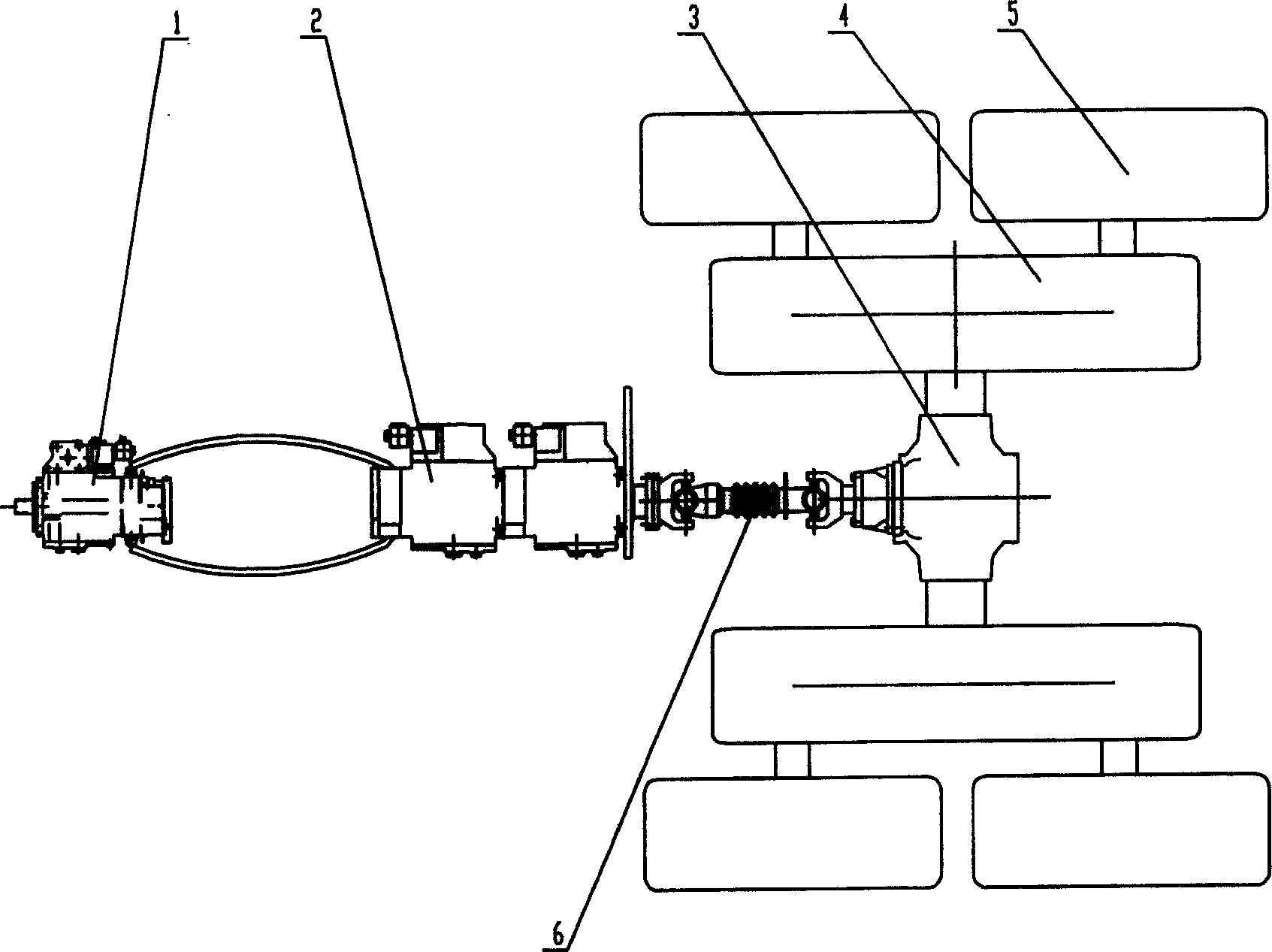
[0014] exist figure 1 Among them, the hydraulic travel driving device of the motor grader in this embodiment is composed of a variable hydraulic pump 1 and a combined hydraulic motor 2 connected through conduits.
[0015] The variable hydraulic pump 1 is installed on the engine of the motor grader and connected with the output shaft of the engine with a coupling. The engine provides power for the variable hydraulic pump 1. The variable hydraulic pump 1 communicates with the combined hydraulic motor 2 through a conduit. This embodiment The combined hydraulic motor 2 is a combination of a variable hydraulic motor and another variable hydraulic motor. The combined hydraulic motor 2 provides driving force for the rear wheel of the motor grader. The combined hydraulic motor 2 is connected with the universal transmission of the grader. The mechanisms 6 are connected, and the universal transmission mechanism 6 is connected with the drive axle 3 of the motor grader with a coupling pie...
Embodiment 2
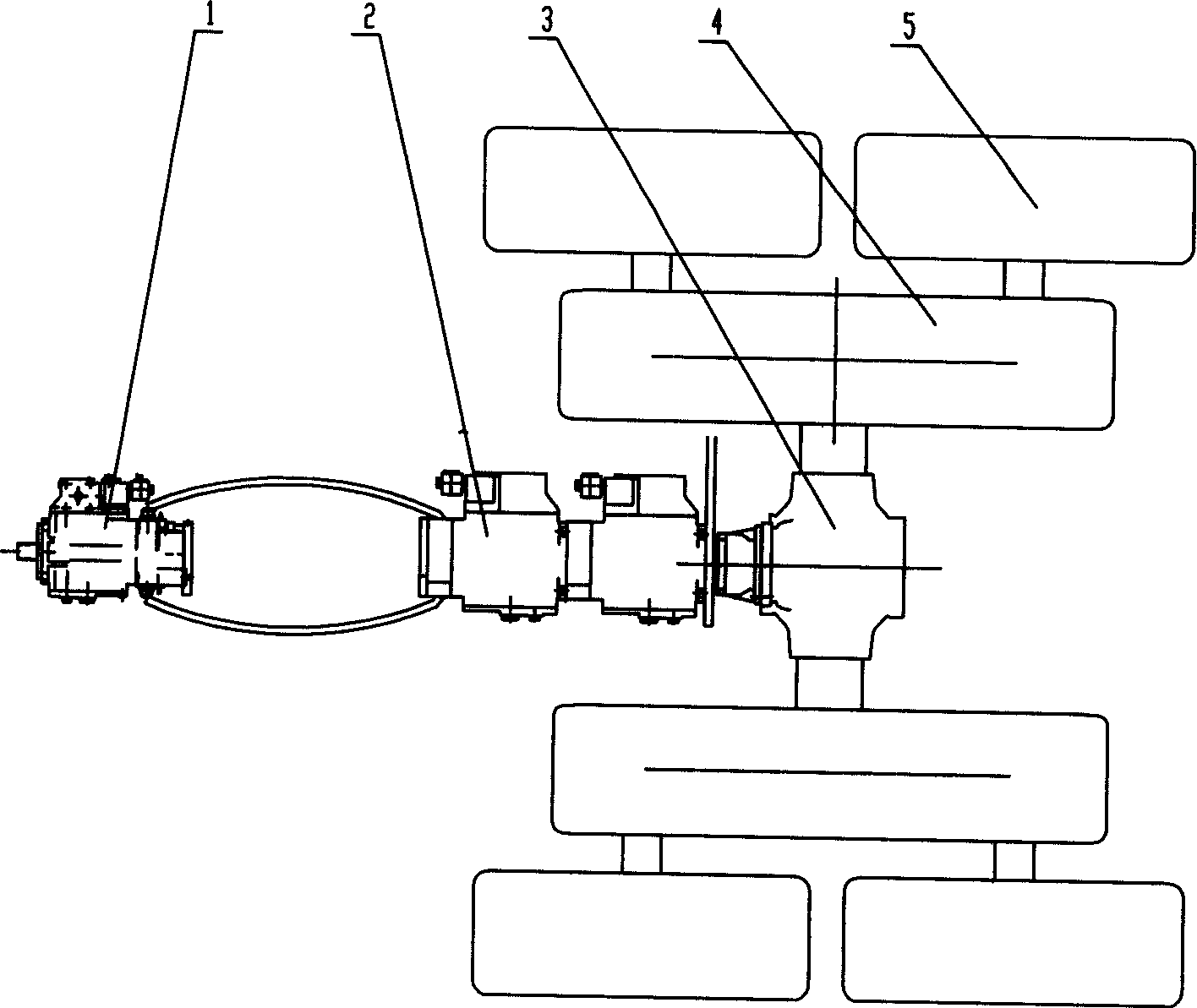
[0017] exist figure 2 Among them, the combined hydraulic motor 2 of this embodiment is connected with the drive axle 3 of the motor grader with a coupling. The combined hydraulic motor 2 is a combination of a variable hydraulic motor and another variable hydraulic motor. The variable hydraulic pump 1 is connected to The combined hydraulic motors 2 are connected, and the combined hydraulic motors 2 provide driving force for the rear wheels of the motor grader. This hydraulic travel driving device of the present embodiment is directly connected with the driving axle 3 of the grader, and the universal transmission mechanism 6 of the grader is removed, the output power loss is reduced, and the structure of the four-wheel drive device of the grader is more compact. Simple, reducing production costs. Other components and the coupling relationship of the components are the same as in Embodiment 1.
Embodiment 3
[0019] In Embodiments 1 and 2, the combined hydraulic motor 2 is a combination of a quantitative hydraulic motor and a quantitative hydraulic motor. The variable hydraulic pump 1 communicates with the combined hydraulic motor 2 through a conduit, and the combined hydraulic motor 2 is the motor grader. The rear wheels provide drive. The other components and the coupling relationship of the components are the same as those in the corresponding embodiments.
PUM
 Abstract
Description
Claims
Application Information
 - R&D
- Intellectual Property
- Life Sciences
- Materials
- Tech Scout
- Unparalleled Data Quality
- Higher Quality Content
- 60% Fewer Hallucinations
Browse by: Latest US Patents, China's latest patents, Technical Efficacy Thesaurus, Application Domain, Technology Topic, Popular Technical Reports.
© 2025 PatSnap. All rights reserved.Legal|Privacy policy|Modern Slavery Act Transparency Statement|Sitemap|About US| Contact US: help@patsnap.com


