Solid femtosecond amplifying device and method thereof

An amplifying device, femtosecond technology, applied in laser parts, electrical components, lasers, etc., can solve the problem of poor spatial coincidence of pump light and seed light, poor laser beam quality and spot roundness, and inability to obtain high pulse energy output and other problems, to achieve the effect of easy production and maintenance, solving low single-pulse energy output, and avoiding complex and poor stability of the system

Pending Publication Date: 2019-06-25
苏州贝林激光有限公司
View PDF0 Cites 0 Cited by
  • Summary
  • Abstract
  • Description
  • Claims
  • Application Information

AI Technical Summary

Problems solved by technology

At the same time, the scheme of the grating pair needs to pass the grating 4 times. Although the diffraction efficiency of a single grating can reach 90%, after 4 passes, the efficiency is only 70%, so the power loss is relatively large.
[0005] In addition, the advantages of fiber amplifiers are high output power and high amplification gain (>10 9 ), the structure is simple and stable, and the production cost is relatively low. The defect is that it is affected by the nonlinearity of the optical fiber, and high pulse energy output cannot be obtained. The single pulse energy is usually <100uJ
In addition, affected by the nonlinear effect of optical fiber, the compressed pulse quality is not high
The advantage of the regenerative amplifier is that the gain of the amplifier is high, and it is easy to obtain >200uJ single pulse energy output. The disadvantage is that the structure of the amplifier cavity is complex, and the pulse timing is very strict. At the same time, it needs to add the emptying function of the electro-optic cavity, which is difficult to manufacture, high in cost, and stable. Sex is not easy to control
The advantage of the slab amplifier is that it has high amplification gain, simple structure, and can obtain high single pulse energy output (>200uJ). However, due to the poor spatial coincidence between the pump light and the seed light, the amplifier output laser beam quality and spot circularity are poor. , many applications are limited

Method used


Image

  • Solid femtosecond amplifying device and method thereof
  • Solid femtosecond amplifying device and method thereof

Examples


Embodiment Construction

[0029] The following will clearly and completely describe the technical solutions in the embodiments of the present invention with reference to the accompanying drawings in the embodiments of the present invention. Obviously, the described embodiments are only some, not all, embodiments of the present invention. The components of the embodiments of the invention generally described and illustrated in the figures herein may be arranged and designed in a variety of different configurations. Accordingly, the following detailed description of the embodiments of the invention provided in the accompanying drawings is not intended to limit the scope of the claimed invention, but merely represents selected embodiments of the invention. Based on the embodiments of the present invention, all other embodiments obtained by those skilled in the art without making creative efforts belong to the protection scope of the present invention.

[0030] It should be noted that like numerals and let...


PUM


Abstract

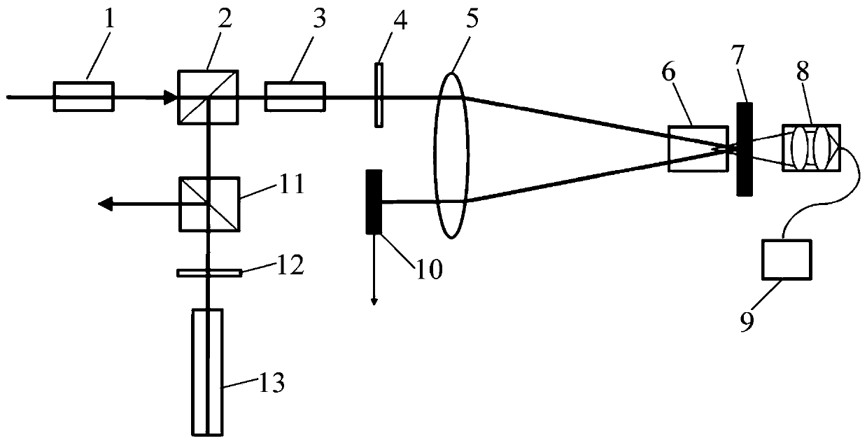
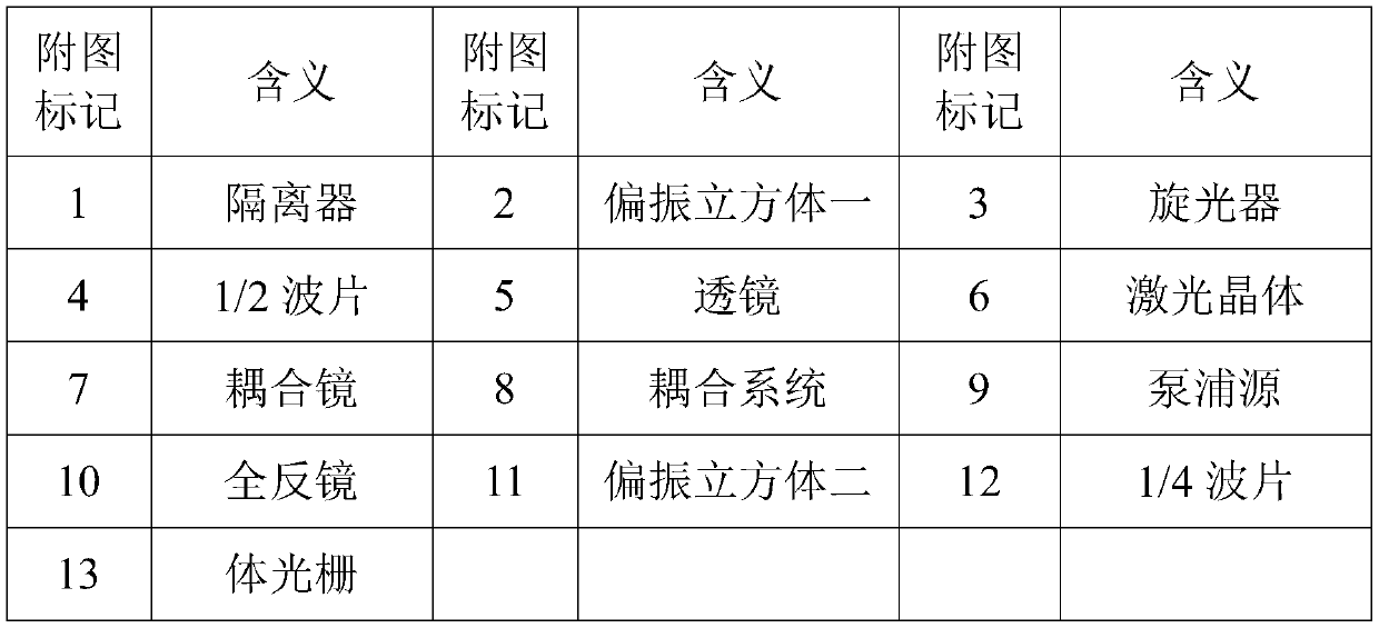
The invention relates to a solid femtosecond amplifying device and a method thereof. An isolator, a polarizing cube I, a rotator and a 1/2 wave plate successively arranged along an optical path are located on one side of a lens. A total reflector is also arranged on the same side of the lens. A laser crystal is arranged on the other side of the lens. A coupling mirror is arranged on the other sideof the laser crystal. The pumping light of a pumping source enters the laser crystal through a coupling system and the coupling mirror. A polarizing cube II, a 1/4 wave plate and a volume grating aresuccessively arranged on the reflection output optical path of the polarizing cube I. The solid amplification technology increases the output single-pulse energy of the amplifier. The four-way traveling wave amplification technology increases the amplifier gain, and tens of watts of amplified light output can be easily achieved. End pumping is used and seed pulse and pumping light achieve a highly spatial coincidence degree so as to achieve excellent output optical pulse quality. A pulse compression scheme uses a volume grating compression technology to achieve high-quality pulse compressionwith one device, thereby increasing power output efficiency.

Description

technical field [0001] The invention relates to a solid femtosecond amplification device and a method thereof. Background technique [0002] At present, due to its extremely high peak power and narrow pulse width, femtosecond lasers have been widely used in fine microprocessing of materials, semiconductor industry, solar photovoltaic, scientific research and other fields. When the femtosecond laser is used for material processing, the light pulse with extremely short duration interacts with the material, and its full energy can be injected into a small area of ​​action at an extremely fast speed, and the thermal effect of the material is well controlled. Second and picosecond laser, using femtosecond laser to process materials, has the advantages of high precision, small heat-affected area, and no burr on the processing edge. The peak power of femtosecond pulses is very high, and direct amplification can easily cause damage to amplifier devices. Therefore, femtosecond laser...

Claims


Application Information

Patent Timeline
Patent Type & Authority Applications(China)
IPC IPC(8): H01S3/00H01S3/10
Inventor 赵裕兴李立卫
Owner 苏州贝林激光有限公司
Why Eureka
Try Eureka