Compression unit of orbiting vane compressor

A technology of rotating blades and vanes, applied in the field of compression components, can solve the problems of deterioration of compressor performance, deterioration of sealing, deterioration of close contact, etc.

Inactive Publication Date: 2006-04-12
LG ELECTRONICS INC
View PDF0 Cites 7 Cited by
  • Summary
  • Abstract
  • Description
  • Claims
  • Application Information

AI Technical Summary

Problems solved by technology

As a result, the tight contact between the arc-shaped opening of the circular vane and the sealing device is significantly deteriorated, and the sealing between the pressurized chambers is also deteriorated
[0020] In addition

Method used


Image

  • Compression unit of orbiting vane compressor
  • Compression unit of orbiting vane compressor
  • Compression unit of orbiting vane compressor

Examples


Embodiment Construction

[0054] Now, preferred embodiments of the present invention will be described in detail with reference to the accompanying drawings.

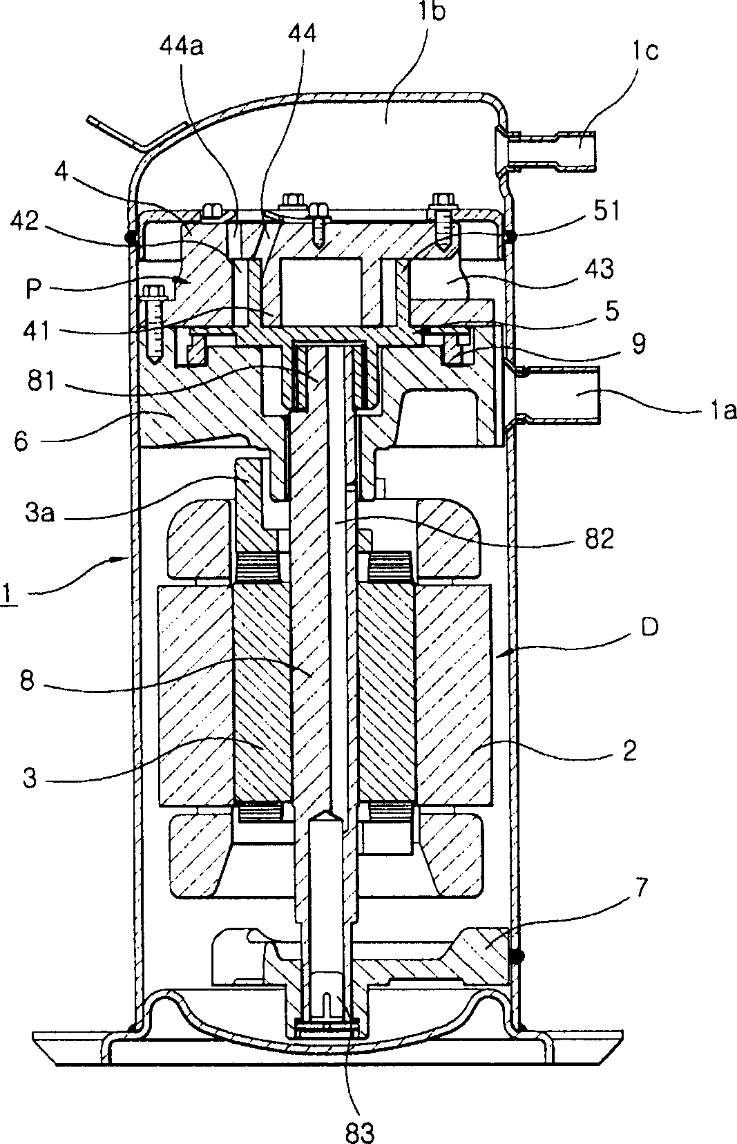
[0055] Figure 4 is a cross-sectional view illustrating a compression part of the rotary vane compressor according to the first preferred embodiment of the present invention.

[0056] Such as Figure 4 As shown, the compression part of the rotary vane compressor according to the present invention comprises a sealing device 54 which, while tightly fitting in the opening formed in the circular vane 51, performs a linear reciprocating movement within the annular space defined in the cylinder. , in order to maintain the seal between a pair of pressurized chambers formed in the annular space 42 and at the same time maintain the seal between the suction chamber and the pressurized chamber also formed in the annular space 42 .

[0057] The sealing device 54 includes a linear slider 541 arranged between the first horizontal contact surface 411 and the...


PUM


Abstract

Disclosed herein is a compression unit of an orbiting vane compressor having improved tight contact between a circular vane and sealing means wherein the sealing means can be easily manufactured. The compression unit compresses refrigerant gas introduced by an orbiting movement of a circular vane in an annular space defined between the inner wall of a cylinder and an inner ring. The compression unit comprises a first horizontal contact surface formed at the outer circumferential surface of the inner ring, a second horizontal contact surface formed at the inner wall of the cylinder while being parallel with the first horizontal contact surface, and a linear slider disposed in an opening formed at the circular vane for performing a linear reciprocating movement along the first and second horizontal contact surfaces.

Description

technical field [0001] The present invention relates to a rotary vane compressor, and more particularly to a compression part of a rotary vane compressor having improved close contact between a circular vane and a sealing device which is easy to manufacture. Background technique [0002] refer to figure 1 , which shows an existing rotary vane compressor. Such as figure 1 As shown, the driving part D and the compressing part P are installed in the housing 1 and the driving part D and the compressing part P are hermetically sealed. The driving part D and the compressing part P are connected to each other through a vertical crankshaft 8 whose upper and lower ends are rotatably supported by the main frame 6 and the auxiliary frame 7, so that the power from the driving part D can be transmitted through the crankshaft 8 to compression part P. [0003] The driving part D includes: a stator 2 fixedly provided between the main frame 6 and the auxiliary frame 7; and a rotor 3 disp...

Claims


Application Information

Patent Timeline
IPC IPC(8): F04C27/00F04C18/344
CPCF04C18/344F04C18/356F04C29/0028F04C2210/26F04C2240/30Y10S415/00Y10S417/00
Inventor 黄善雄刘东原
Owner LG ELECTRONICS INC
Why Eureka
Try Eureka