Electro-optical device, method of driving electro-optical device, and electronic apparatus

An electro-optical device and driving method technology, applied in optics, nonlinear optics, cathode ray tube indicators, etc., can solve the problems of different duty ratios, complex structures, etc.

Inactive Publication Date: 2006-04-12
SEIKO EPSON CORP
View PDF1 Cites 29 Cited by
  • Summary
  • Abstract
  • Description
  • Claims
  • Application Information

AI Technical Summary

Problems solved by technology

[0006] However, in the above configuration, it is necessary to make the duty ratio different when comparing the modulated clock signal used when displaying a low-resolution image with the reference clock signal used when displaying a normal high-resolution imag...

Method used


Image

  • Electro-optical device, method of driving electro-optical device, and electronic apparatus
  • Electro-optical device, method of driving electro-optical device, and electronic apparatus
  • Electro-optical device, method of driving electro-optical device, and electronic apparatus

Examples


Embodiment Construction

[0026] Hereinafter, embodiments of the present invention will be described with reference to the drawings. The electro-optical device of this embodiment is configured by adhering an element substrate on which various transistors or pixel electrodes are formed and a transparent counter substrate having a common electrode with a fixed gap between them, and sandwiching liquid crystal in the gap.

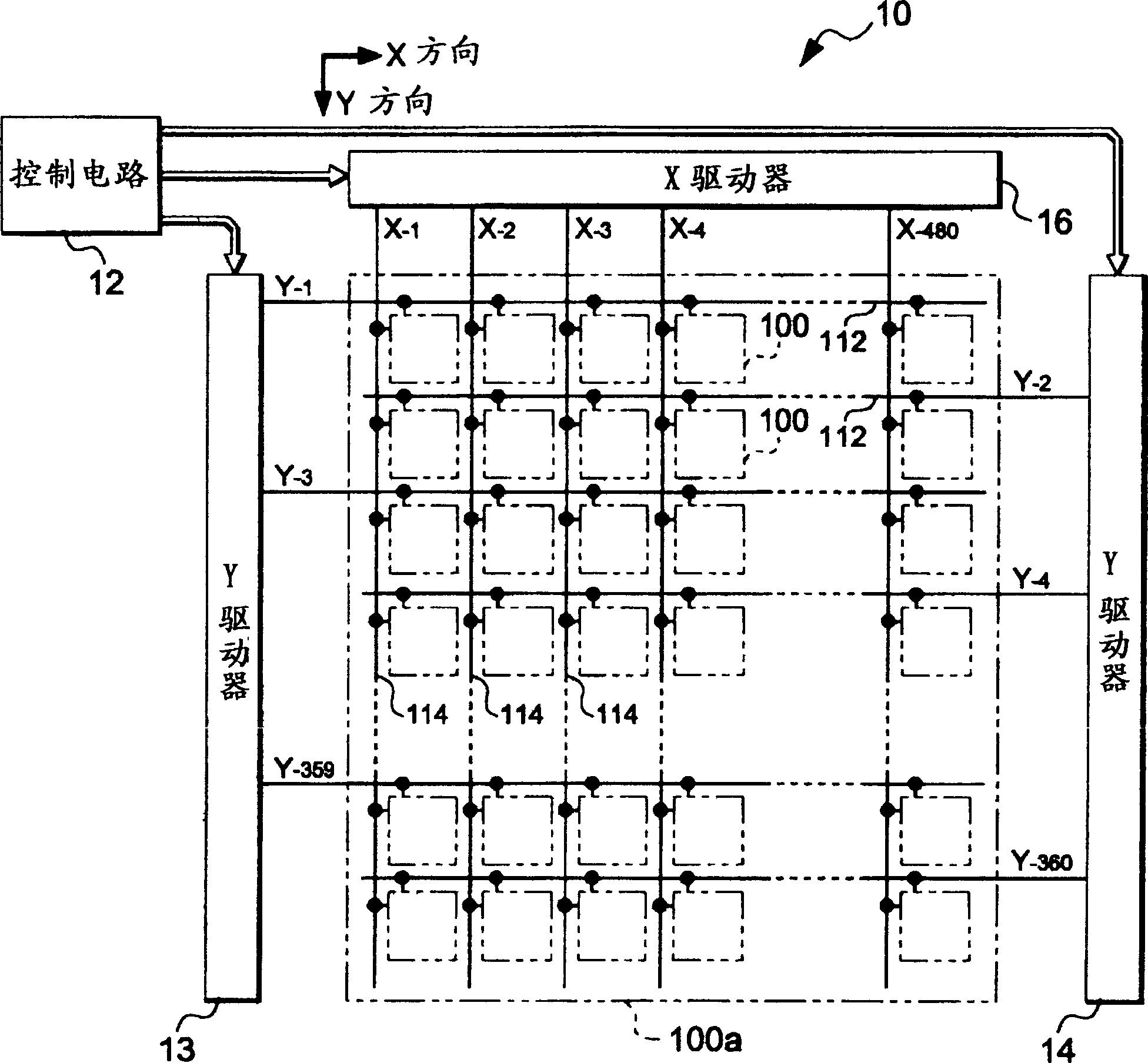
[0027] figure 1 is a block diagram showing the electrical configuration of the electro-optical device 10 .

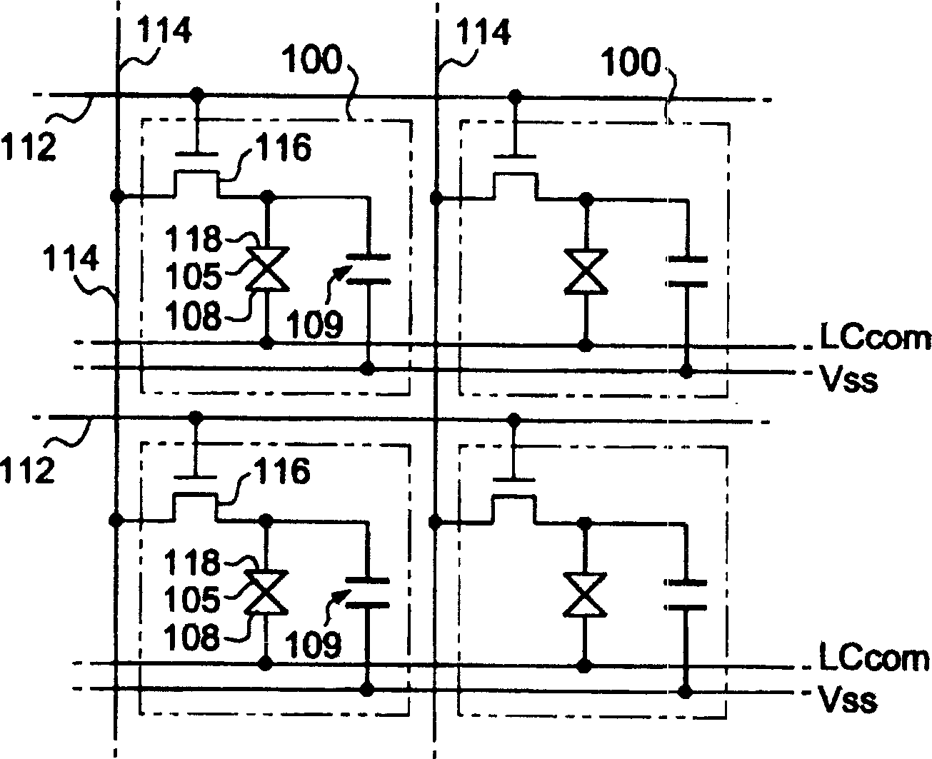
[0028] As shown in the figure, the electro-optical device 10 has a control circuit 12, Y drivers 13, 14, and an X driver 16. At the same time, 360 scanning lines 112 are extended in the horizontal direction (X direction). On the other hand, 480 data lines The wire 114 extends in the longitudinal direction (Y direction). Then, the pixel circuits 100 are arranged corresponding to the intersections of the scanning lines 112 and the data lines 114 . Therefore, in the present embo...


PUM


Abstract

To provide a technique for converting vertical resolution with a simple constitution. The electro-optical device is provided with a Y driver 13 which selects scanning lines 112 of odd numbered lines in the specified order and a Y driver 14 which selects scanning lines 112 of even numbered lines in the specified order. Therein, the Y driver 13 comprises a shift register 131 which shifts a transfer starting signal SPL according to a clock signal [Phi]L and, thereby, generates a logic signal for selecting scanning lines in the specified order, and an output control circuit 133 which narrows the logic signal into the L-level pulse width of an enable signal EnL and outputs the logic signal as a scanning signal for selecting the scanning lines. The Y driver 14 is also constituted in the similar manner. In such a constitution, in the case of the normal resolution mode, enable signals of which the phases are different from each other are supplied to the Y drivers 13, 14 and the scanning lines of the odd numbered lines and the even numbered lines are alternately selected. On the other hand, in the case of the low resolution mode, enable signals of approximately the same phase are supplied to the Y drivers 13, 14 and the two scanning lines of the adjacent odd numbered line and even numbered line are selected simultaneously.

Description

technical field [0001] The present invention relates to a technique for changing the display resolution of an electro-optic device. Background technique [0002] In electronic devices such as mobile phones, since the increase in the amount of information requires high-density display of images, the resolution of display devices has been increasing year by year. On the other hand, it is difficult to distribute high-definition moving images due to insufficient information transfer speed of communication devices and the like, so low-resolution images are often distributed at present. [0003] Here, when a low-resolution image is displayed on a high-resolution display device, only a part of the screen is used for display, so a resolution conversion device is required. Conventionally, a DSP (Digital Signal Processor) or the like has been used for such a conversion device, but there are problems such as high cost and delay in conversion processing. [0004] For this reason, ther...

Claims


Application Information

Patent Timeline
IPC IPC(8): G09G3/20G09G5/391
CPCG09G2340/145G09G2310/0205G09G2340/0414G09G3/3677G09G3/20G09G3/36G02F1/133
Inventor 藤田伸
Owner SEIKO EPSON CORP
Why Eureka
Try Eureka