
Chemical amplification type positive resist composition

A photoresist and composition technology, applied in optics, optomechanical equipment, instruments, etc., can solve the problems of fluctuation in the size of the magnetic film pattern, insufficient resolution of the photoresist pattern, insufficient depth of focus, etc., and achieve good reproducibility Effect

Active Publication Date: 2006-04-12
TOKYO OHKA KOGYO CO LTD
View PDF0 Cites 5 Cited by
  • Summary
  • Abstract
  • Description
  • Claims
  • Application Information

AI Technical Summary

Problems solved by technology

However, if a chemically amplified photoresist is used in this method, the resolution of the photoresist pattern is insufficient and the width of the depth of focus is insufficient, meaning that the tapered photoresist pattern cannot be stably reproduced.
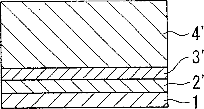
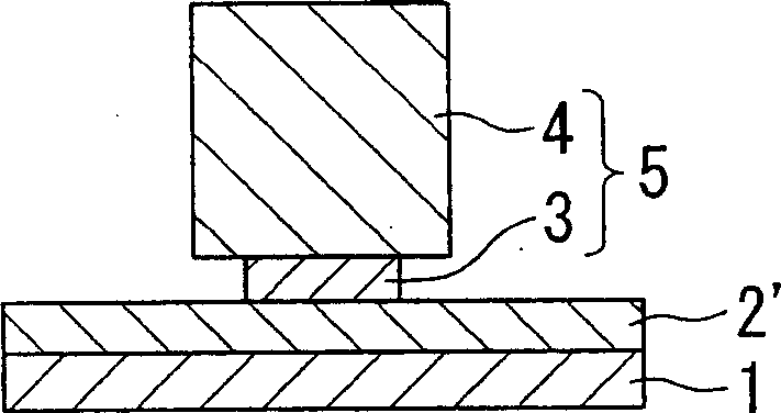
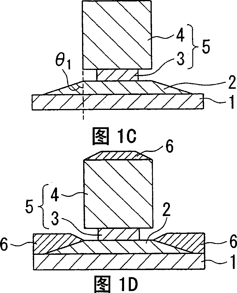
Therefore, if such a photoresist pattern is used and then ion milling or plating is performed, a large number of problems may occur, including inability to form a fine magnetic film pattern, fluctuations in the size of the magnetic film pattern on the substrate, fluctuations in the magnetic film pattern on the substrate, etc. The inclination angle of the side wall (θ in the description below 2 ' and θ 3 ')fluctuation

Method used


Image

  • Chemical amplification type positive resist composition
  • Chemical amplification type positive resist composition
  • Chemical amplification type positive resist composition

Examples


Embodiment

[0147] The embodiments of the present invention are described below, but the scope of the present invention will never be affected by the following

[0148] Limitations of the embodiment.

[0149] [Examples 1 to 4 (first mode), comparative example 1]

[0150]

[0151] By changing the amount of component (A), five different positive photoresist compositions of Examples 1 to 4 and Comparative Example 1 were prepared in the following method.

[0152] That is, in component (D), component (A), component (B), component (C), component (E) and any other components are uniformly dissolved to obtain a positive photoresist composition .

[0153] As for the component (A), anthracene methanol is used, as shown in the following [Formula 1]. In Examples 1 to 4, by using 4.0, 4.5, 5.0, and 5.5 parts by weight of component (A) per 100 parts by weight of component (B), respectively, the mixed amount of component (A) was changed in a stepwise manner . In Comparative Example 1, the component (A) was...

Embodiment 5 to 12

[0177] [Embodiments 5 to 12 (Second Mode)]

[0178]

[0179] By changing the amount of component (A), 8 different positive photoresist compositions of Examples 5 to 12 were prepared in the following method.

[0180] That is, in addition to changing the component (A) in a stepwise manner by using 0.2, 0.5, 1.0, 1.5, 2.0, 3.0, 4.0, and 4.5 parts by weight of the component (A) for every 100 parts by weight of the component (B), respectively ( Except for the mixing amount of A), the positive photoresist compositions of Examples 5 to 12 were prepared in the same manner as in Example 1. The positive photoresist compositions of Examples 11 and 12 are the same as the compositions of Examples 1 and 2, respectively.

[0181] Then, using a spin coater, each of the positive photoresist compositions thus obtained was applied to the surface of the silicon wafer, and then pre-baked and dried on a hot plate at 100°C for 90 seconds, thereby forming a film with a thickness of 800 nm Photoresist fi...


PUM

PropertyMeasurementUnit
thicknessaaaaaaaaaa
angleaaaaaaaaaa
transmittivityaaaaaaaaaa

Abstract

A positive resist composition that is capable of forming fine resist patterns, capable of appropriately controlling the angle of taper configuration of resist patterns and capable of forming resist patterns excelling in focal depth breadth. This positive resist composition consists of a chemical amplification type positive resist composition and realizes a transmission of 248 nm wavelength light through 0.3 mum thick resist film of 20 to 75%.

Description

Technical field [0001] The present invention relates to a positive photoresist composition with suppressed light transmittance, and a method for forming a magnetic film pattern using this photoresist composition, wherein the specific photoresist composition formed from the chemically amplified positive photoresist composition The light transmittance of the photoresist film to radiation with a wavelength of 248 nm is specified in a specific range. Background technique [0002] The increase in the recording density of magnetic recording media continues to occur at a significant rate, and in order to meet the future demand for further increase in the recording density, further miniaturization of the magnetic head must be achieved. [0003] For example, in the readout part of the magnetic head (the magnetic head part for readout), not only must a fine photoresist pattern (isolation pattern) be formed to be able to form a fine photoresist pattern, but also the shape of the fine magnet...

Claims


Application Information

Patent Timeline
Patent Type & Authority Applications(China)
IPC IPC(8): G03F7/039H01L21/30
Inventor 新堀博
Owner TOKYO OHKA KOGYO CO LTD
Learn More