Ultrasonic probe and ultrasonographic device
A diagnostic equipment, ultrasonic technology, applied in the direction of ultrasonic/sonic/infrasonic diagnosis, ultrasonic diagnosis, infrasonic diagnosis, etc., to achieve the effect of low cost
- Summary
- Abstract
- Description
- Claims
- Application Information
AI Technical Summary
Problems solved by technology
Method used
Image
Examples
Embodiment 1
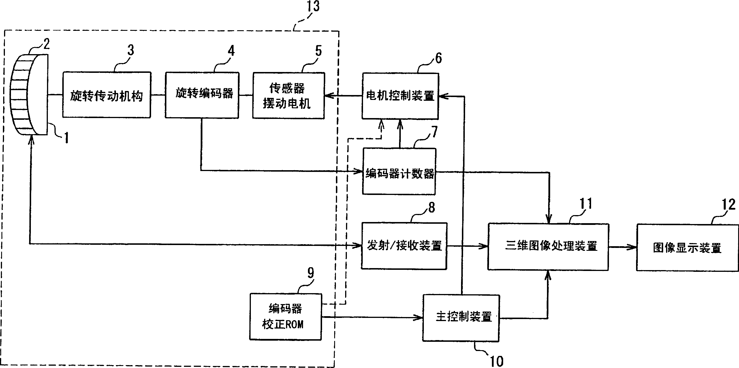
[0037] figure 1 is a block diagram showing an example of the configuration of an ultrasonic diagnostic apparatus according to Embodiment 1 of the present invention. figure 1 The ultrasonic diagnostic apparatus shown in will also be used in the various embodiments described below.
[0038] exist figure 1 Among them, the ultrasonic diagnostic apparatus according to the present embodiment includes: an ultrasonic transceiver 1 having a plurality of transceiver elements 2 arranged in an array, the transceiver elements 2 transmit ultrasonic beams into the living body, and echo ultrasonic waves from tissues in the living body converted into electrical signals. Each transceiver element 2 is excited by a transmit pulse provided by the transmit / receive device 8 . The transmission / reception device 8 is controlled to provide transmission pulses with different phases to some or all of the transceiver elements 2 arranged in the ultrasonic transceiver 1, so that the transmission pulses...
Embodiment 2
[0053] Next, refer to the attached figure 1 Embodiment 2 of the present invention is described in detail with Embodiment 1.
[0054] Generally, the wobble scan is mostly performed as a reciprocating scan. The purpose of using this method is to form a three-dimensional image in more real time. Also in this case, even when the count value provided by the encoder counter 7 is equal on the forward path of the wobble scan and on its return path, the actual wobble scan angle is often different, which is In addition to the problems mentioned above, another problem arises from the mechanical scanning method.
[0055] This is mainly caused by the rotating shaft connecting the transceiver swing motor 5 and the rotation transmission mechanism of the ultrasonic transceiver 1 . For example, in a rotary transmission mechanism using gears, when the gears are rotated forward and backward, the angle of rotation of the driven gear relative to the rotation angle of the motor shaft is differe...
Embodiment 3
[0059] Next, refer to the attached figure 2 to 6 describe in detail an ultrasonic diagnostic apparatus as Embodiment 3 of the present invention which forms a more accurate three-dimensional image using the ultrasonic probe 13 including the above-mentioned encoder correction ROM 9 and the like.
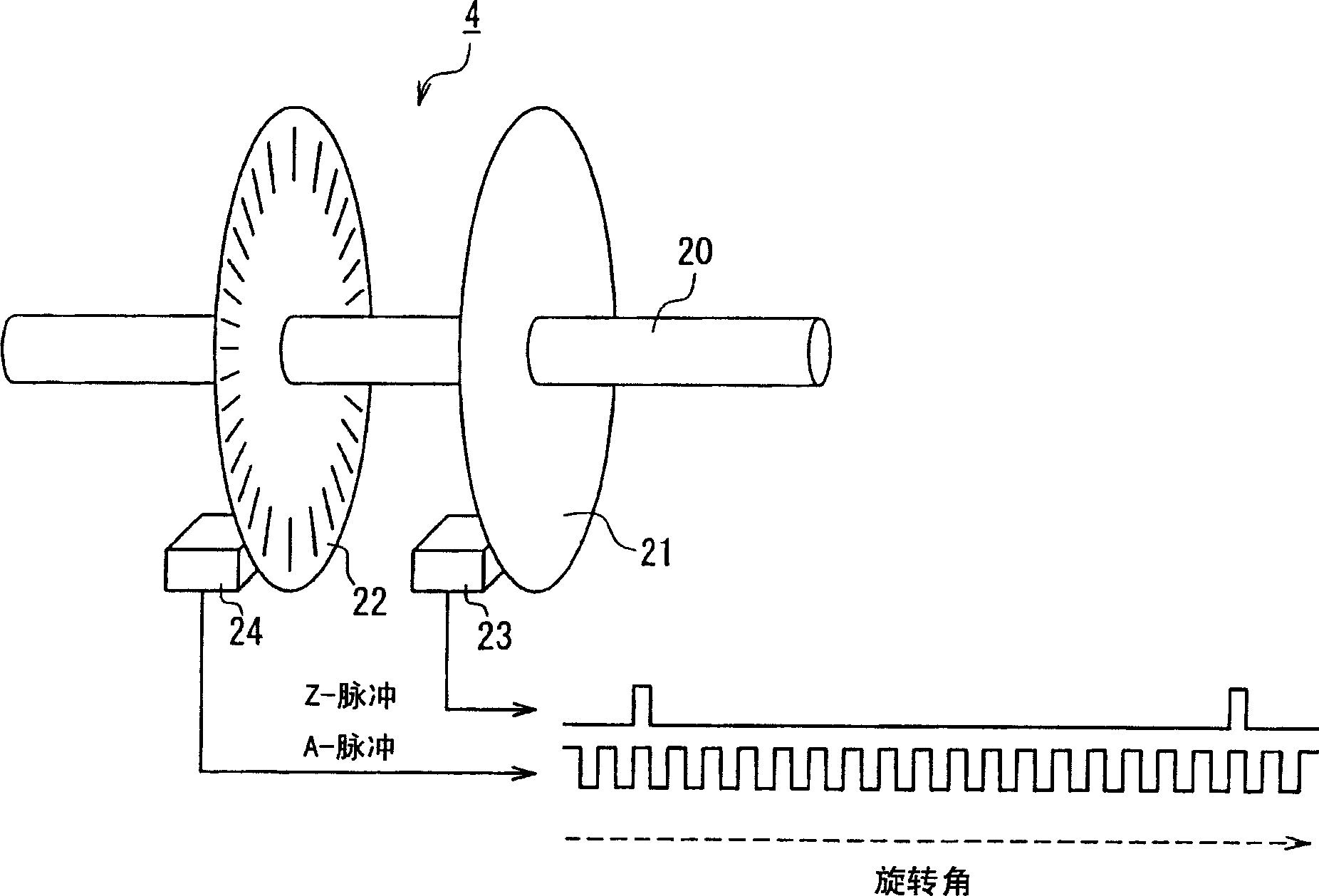
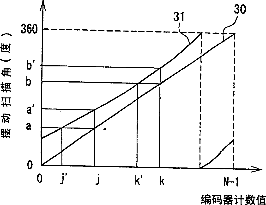
[0060] In the encoder correction ROM 9 of the ultrasonic diagnostic apparatus according to the present embodiment, the image 3 The correction value shown is 31. exist image 3 Among them, the straight line 30 represents the situation that the swing scanning angle of the ultrasonic transceiver 1 corresponding to the count value of the encoder counter 7 is an ideal value, and wherein the encoder counter 7 is an addition counter using a rotary encoder 4, and the rotary encoder 4 transmits and receives N A-pulses are generated during one revolution of the rotating shaft of the swing motor 5, and one Z-pulse is generated when the angle of the rotating shaft is 0 degrees. In addition, t...
PUM
 Abstract
Description
Claims
Application Information
 - R&D
- Intellectual Property
- Life Sciences
- Materials
- Tech Scout
- Unparalleled Data Quality
- Higher Quality Content
- 60% Fewer Hallucinations
Browse by: Latest US Patents, China's latest patents, Technical Efficacy Thesaurus, Application Domain, Technology Topic, Popular Technical Reports.
© 2025 PatSnap. All rights reserved.Legal|Privacy policy|Modern Slavery Act Transparency Statement|Sitemap|About US| Contact US: help@patsnap.com


