Multicarrier receiver and transmitter with delay correcting function

A multi-carrier and receiver technology, applied in the field of transmitters, can solve problems such as difficulty in mass production, and achieve the effect of reducing cost and size, and reducing precision requirements

Inactive Publication Date: 2006-04-26
KOKUSA ELECTRIC CO LTD
View PDF1 Cites 6 Cited by
  • Summary
  • Abstract
  • Description
  • Claims
  • Application Information

AI Technical Summary

Problems solved by technology

However, in the conventional method, every time the number of SAW filter stages increases by 1, the gain decreases by about 10dB, so an additional amplifier is required
Thus, ...

Method used


Image

  • Multicarrier receiver and transmitter with delay correcting function
  • Multicarrier receiver and transmitter with delay correcting function
  • Multicarrier receiver and transmitter with delay correcting function

Examples


Embodiment Construction

[0055] Below in conjunction with accompanying drawing, explain the preferred embodiment of the present invention.

[0056] first preferred embodiment

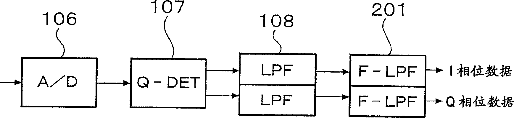
[0057] figure 1 The configuration diagram of shows the basic components of the first embodiment of the multi-carrier receiver according to the present invention, it only shows the Figure 16 The different components, and their surroundings. Reference numeral 201 denotes an F-LPF (Fractional Low-Pass Filter). corresponds to Figure 16 Constituent parts of the components shown are assigned the same reference numerals, respectively, so repeated descriptions are omitted here.

[0058] In this figure, the first embodiment includes Figure 16 F-LPF 201 in a stage following LPF 108 in the configuration shown. Incidentally, it is also possible to combine LPF 108 and F-LPF 201 so that LPF 108 can participate in the role played by F-LPF 201 . However, these functions are shown in component form for ease of understanding. Any one...


PUM


Abstract

A multi-carrier receiver receiving N carrier frequencies, including N A/D converters, each A/D converter performs analog-to-digital conversion on the received signal of each carrier at a sampling rate fs; N quadrature detection 2N LPFs, which only allow the required frequency bands output by N quadrature detectors to pass through; and N delay correction devices, Each correcting device uses a fractional delay filter to correct the processing delay deviation of each carrier in the multi-carrier receiver, and the corrected time unit is less than 1/fs. The delay correction device has, for example, an M-stage shift register that operates at fs and produces a delay of M/fs; and a fractional delay filter that operates at fs and includes an even number of tap coefficients that produces a delay that differs from M/fs 0.5/fs.

Description

technical field [0001] The present invention relates to a multi-carrier receiver and transmitter with a delay correction function, and more particularly, the present invention relates to a multi-carrier receiver which suppresses the delay of each carrier in the receiving section when processing multi-carriers Deviation, and such a transmitter, it has a delay correction function, corrects the delay between transmission and feedback, and performs distortion analysis. Background technique [0002] Figure 15 The configuration diagram of shows an example of a conventional multi-carrier receiver. [0003] In the same figure, reference numeral 101 refers to a duplexer (DUP), which has a filter, and one end is connected to an antenna (not shown) capable of transmitting and receiving multi-carriers. The transmitted signal to the antenna and the received signal from the antenna. [0004] Reference numeral 102 designates a low noise amplifier which amplifies a received signal to a d...

Claims


Application Information

Patent Timeline
IPC IPC(8): H04L27/26H04L5/06H04L25/03
Inventor 宫谷彻彦冈田贵史
Owner KOKUSA ELECTRIC CO LTD
Why Eureka
Try Eureka