Novel punch head
A punch, a new type of technology, applied in the direction of presses, manufacturing tools, etc., can solve the problems of affecting the efficiency of processing and rising processing costs, and achieve the effect of easy replacement and non-damage
- Summary
- Abstract
- Description
- Claims
- Application Information
AI Technical Summary
Problems solved by technology
Method used
Image

Examples
Embodiment Construction
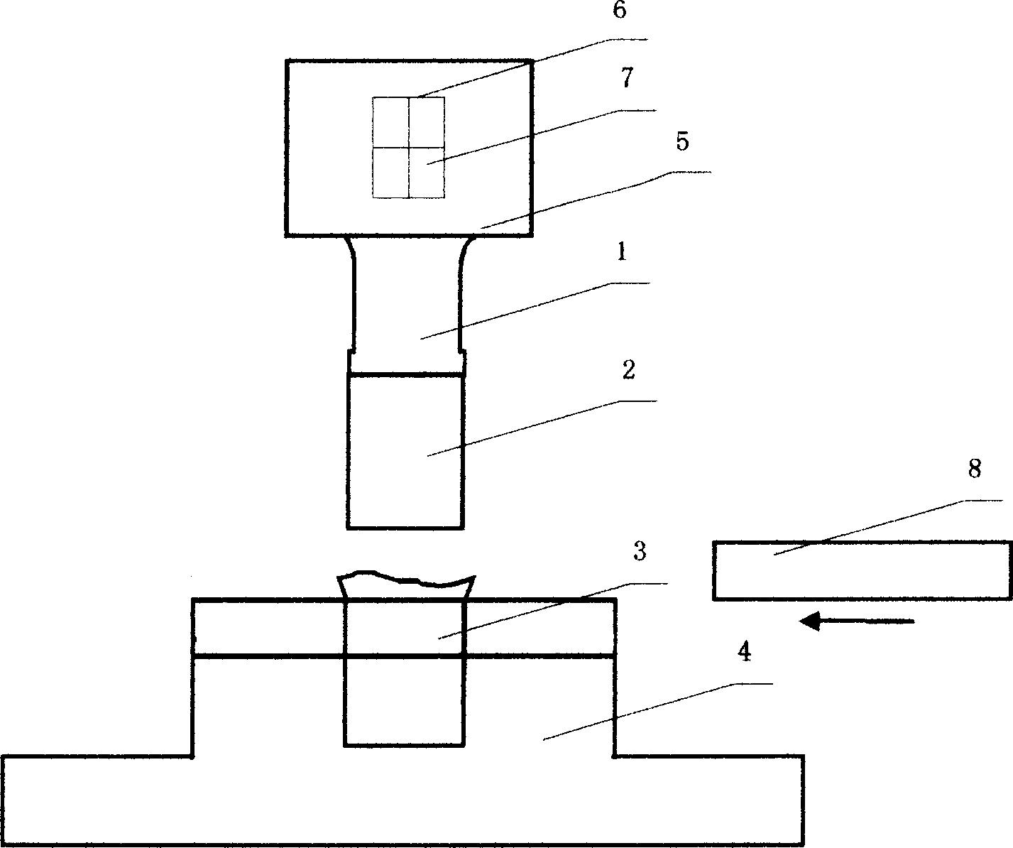
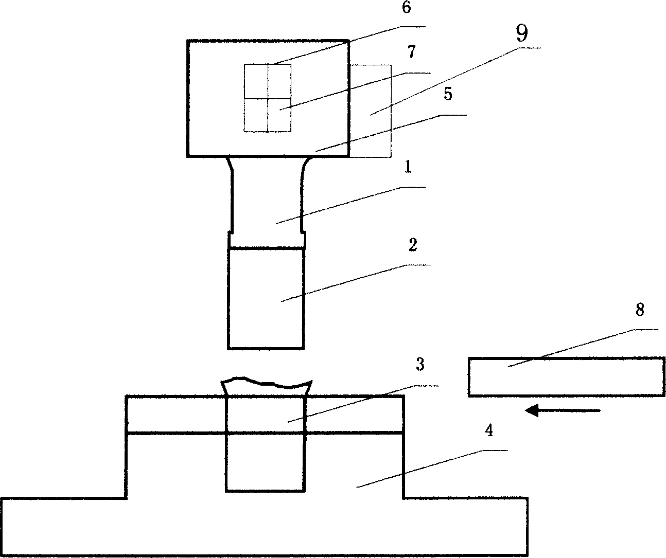
[0009] Below in conjunction with accompanying drawing, the present invention is further described:
[0010] Such as figure 1 The middle is a specific embodiment of the present invention. A square hole 6 is provided in the punch holder 5, a permanent magnet 7 is installed in the hole, and a punch 1 is fixed under the punch holder 5. Because the punch holder 5 is affected by the permanent magnet 7, the magnetic force is concentrated on the end of the punch 1. The shear core 2 used for positioning during cutting is placed on the end of the punch 1 and is magnetically adsorbed on the punch 1 . On the working table of the punching machine, a lower mold base 4 is installed, and the middle part of the lower mold base 4 is a square counterbore with a shape corresponding to the shape of the workpiece, which is used to place the workpiece. Riser. Now the punch 2 is just above the square counterbore on the lower die base 4 . After placing the workpiece 3 in the above-mentioned squar...
PUM
 Abstract
Description
Claims
Application Information
 - Generate Ideas
- Intellectual Property
- Life Sciences
- Materials
- Tech Scout
- Unparalleled Data Quality
- Higher Quality Content
- 60% Fewer Hallucinations
Browse by: Latest US Patents, China's latest patents, Technical Efficacy Thesaurus, Application Domain, Technology Topic, Popular Technical Reports.
© 2025 PatSnap. All rights reserved.Legal|Privacy policy|Modern Slavery Act Transparency Statement|Sitemap|About US| Contact US: help@patsnap.com