Holding tool for a processing head in a laser processing machine with several anti-colliding elements having means for adjusting the loosening load

A technology of laser processing machine and laser processing head, which is applied in the direction of metal processing machinery parts, auxiliary devices, laser welding equipment, etc.

Active Publication Date: 2006-05-03
TRUMPF WERKZEUGMASCHINEN GMBH & CO KG
View PDF1 Cites 6 Cited by
  • Summary
  • Abstract
  • Description
  • Claims
  • Application Information

AI Technical Summary

Problems solved by technology

[0004] The known interface only has the function of mechanical fixing of the laser cutting head and delivery of cutting gas, and includes a limited collision protection

Method used


Image

  • Holding tool for a processing head in a laser processing machine with several anti-colliding elements having means for adjusting the loosening load
  • Holding tool for a processing head in a laser processing machine with several anti-colliding elements having means for adjusting the loosening load
  • Holding tool for a processing head in a laser processing machine with several anti-colliding elements having means for adjusting the loosening load

Examples


Embodiment Construction

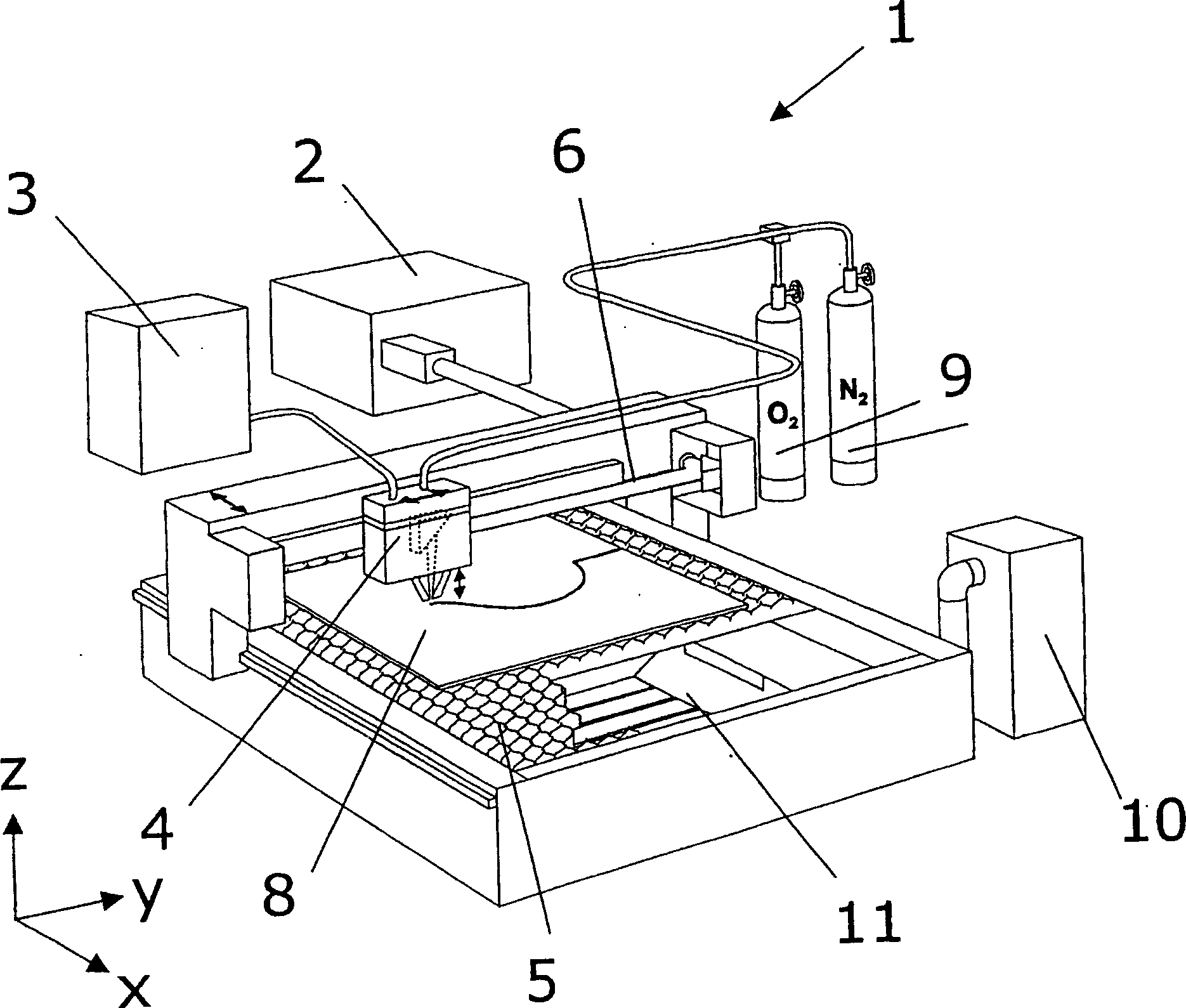
[0019] Depend on figure 1 The basic structure of a laser processing plant 1 for laser cutting with a CO 2 Laser 2, a control device 3, a laser processing head 4 and a workpiece support 5. A generated laser beam 6 is directed onto the laser processing head 4 and directed onto the workpiece 8 by means of deflection mirrors.

[0020] The laser beam 6 must penetrate the workpiece 8 before forming the usual cutting seam. The metal plate 8 must be melted or oxidized in spots at one point and the melt must be blown out. The piercing process can be performed quickly (ie with full laser power) or slowly (via a so-called "ramp").

[0021] When piercing at a slow speed with a ramp, the laser power can be gradually increased-decreased and kept constant in a certain time interval until the pierced hole is produced. Both piercing and laser cutting are assisted by the addition of a gas. Oxygen, nitrogen, compressed air and / or, depending on the application, special gases can be used as c...


PUM


Abstract

The clamping device of the processing head (4) on the laser processing machine has a collision protection device for releasing the clamping when the processing head (4) collides. The crash protection device is provided with crash protection components (21, 21') with regulation of the released crash force.

Description

technical field [0001] The invention relates to a clamping device for a processing head on a laser processing machine, which has a crash protection device for releasing the clamping in the event of a collision of the processing head. Background technique [0002] A crash protection device for a laser processing head of a laser processing machine is known, for example, from DE 197 01 516 C1, which includes a releasable coupling of the laser processing head on a support. [0003] A collision of the laser processing head with the workpiece or a device should not result in any damage to the machine or the workpiece. Deviations of the laser processing head from its defined position after a collision must be detected precisely. The replacement of the processing head should be easily realized on the same interface. [0004] The known interface only has the function of mechanical fixing of the laser cutting head and delivery of the cutting gas, and includes a limited collision pro...

Claims


Application Information

Patent Timeline
Patent Type & Authority Applications(China)
IPC IPC(8): B23K26/42B23K26/00B23Q11/00
CPCB23K26/0884B23K26/1476B23K26/1482B23K26/1488B23K37/0235B23K26/702
Inventor 于尔根-米夏埃多·魏克梅尔廷·兰贝特
Owner TRUMPF WERKZEUGMASCHINEN GMBH & CO KG
Why Eureka
Try Eureka