
Photoelectricity triggering and detecting system for static reactive-load compensation equipment based on multi-mode optical fibre

A photoelectric trigger and photoelectric detection technology, applied in reactive power compensation, reactive power adjustment/elimination/compensation, electronic circuit testing, etc., to achieve reliable communication, fast thyristor operation status, good promotion value and application prospects

Active Publication Date: 2006-05-03
CHINA ELECTRIC POWER RES INST +1
View PDF0 Cites 15 Cited by
  • Summary
  • Abstract
  • Description
  • Claims
  • Application Information

AI Technical Summary

Problems solved by technology

These technical difficulties determine that the development of the photoelectric trigger and detection system based on multimode fiber is very technically difficult. At present, the photoelectric trigger and detection system based on multimode fiber has not seen the same or similar technology at home and abroad.

Method used


Image

  • Photoelectricity triggering and detecting system for static reactive-load compensation equipment based on multi-mode optical fibre
  • Photoelectricity triggering and detecting system for static reactive-load compensation equipment based on multi-mode optical fibre
  • Photoelectricity triggering and detecting system for static reactive-load compensation equipment based on multi-mode optical fibre

Examples


Embodiment Construction

[0030] The present invention will be described in detail below in conjunction with the accompanying drawings.

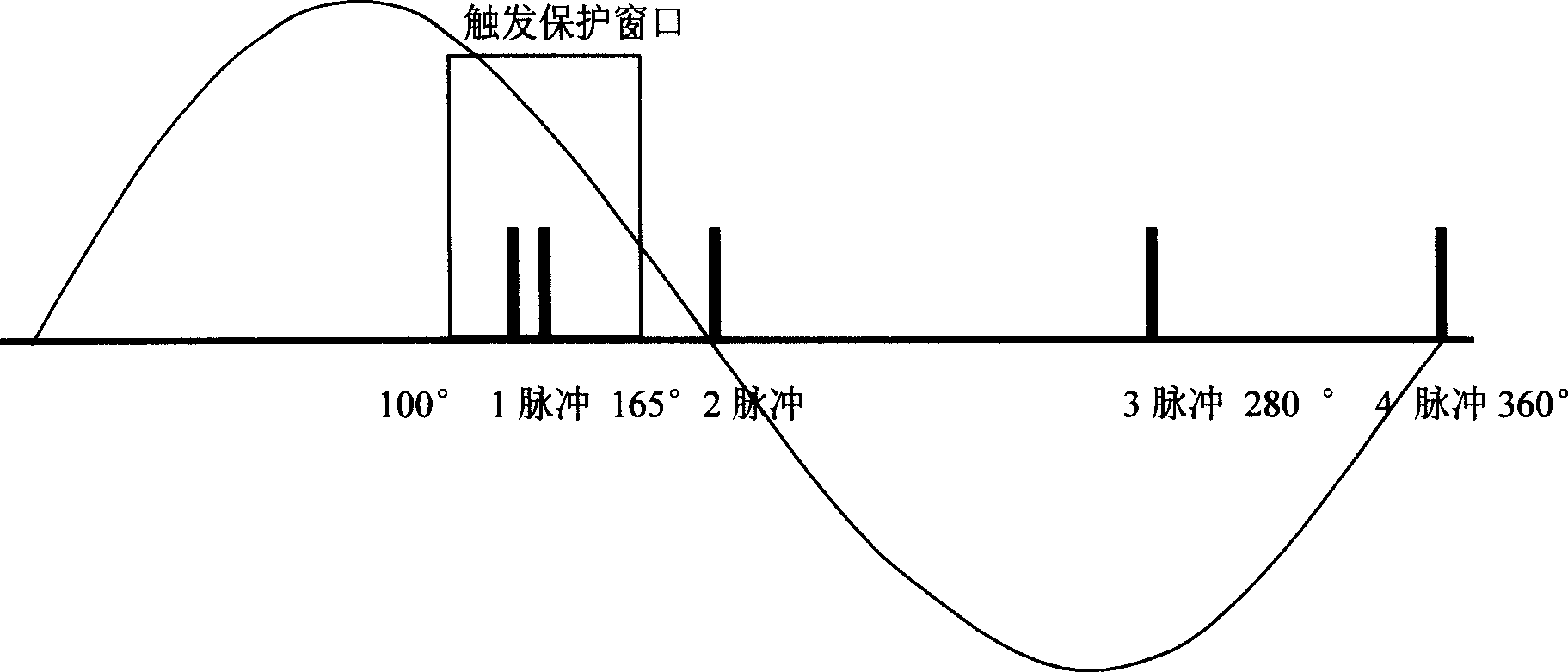
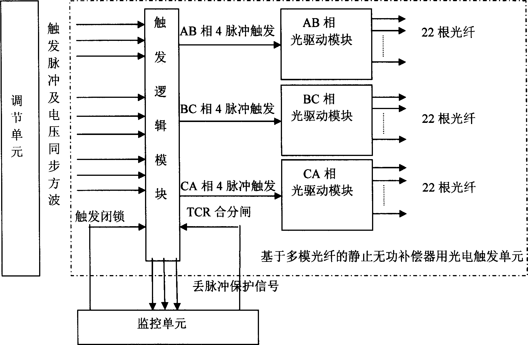
[0031] Referring to accompanying drawings 2 and 3, the photoelectric trigger and detection system based on multimode fiber includes a photoelectric trigger unit and a photoelectric detection unit. The photoelectric trigger unit includes: trigger logic module, AB phase, BC phase, CA phase optical drive module and trigger optical fiber.

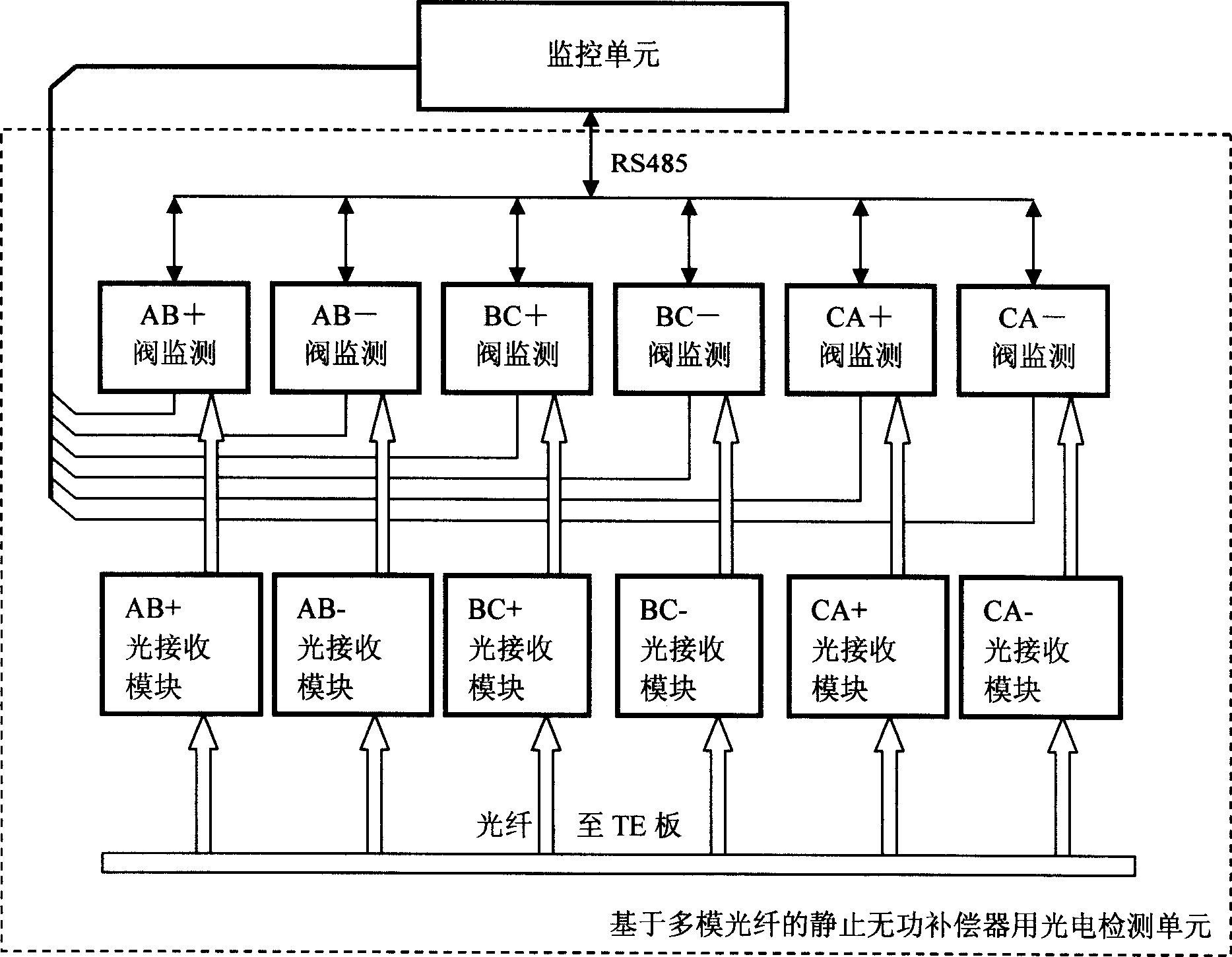
[0032] The photoelectric detection unit includes a valve intelligent detection module, a light receiving module and a return optical fiber.

[0033] The photoelectric detection unit includes 6 valve detection modules, AB+, AB-, BC+, BC-, CA+, CA-light receiving modules and optical fibers.

[0034] The adjustment unit of the SVC control system obtains the thyristor trigger phase by calculating the three-phase voltage and current of the compensated system, and sends it to the photoelectric trigger unit in the form of a narrow single pu...


PUM


Abstract

The invention relates to a photoelectric trigger and test system of a multimode optical fiber. It comprises a photoelectric trigger unit and a photoelectric test unit. The photoelectric trigger unit comprises: a trigger logic module, AB phase, BC phase, CA phase optical driving module and optical fiber. The photoelectric test unit comprises: six valve test module, AB+íóAB-íóBC+íóBC-íóCA+íóCA- optical receiving module and optical fiber. The photoelectric trigger unit and the photoelectric test unit have auto encoding optical pulse trigger transistor; the optical pulse feedback intelligently test the transistor running condition, the electric trigger pulse test and the PT off test and the master-slave mode distribution serial communication of the upper position machine.

Description

technical field [0001] The present invention relates to static var compensator (SVC) in power system and power electronics technology, especially a photoelectric trigger and detection system for static var compensator based on multimode optical fiber, also known as valve-based electronic equipment (VBE- Valve Base Equipment). Background technique [0002] The photoelectric trigger and detection system for static var compensator based on multimode fiber is an important part of SVC, also known as valve-based electronic equipment VBE. It is a device that triggers the conduction of the thyristor valve group and detects the operating state of the thyristor valve group. It can be used not only in static var compensators (SVC), but also widely used in power plants with thyristor valve groups such as high-voltage direct current transmission (HVDC). in electronic equipment. When the thyristor valve group of the static var compensator is running, the VBE control system of the valve-...

Claims


Application Information

Patent Timeline
IPC IPC(8): H02J3/18G01R31/28H03K17/79H03K17/968
CPCY02E40/30
Inventor 赵刚汤广福任孟干蓝元良
Owner CHINA ELECTRIC POWER RES INST
Learn More