Photoelectricity triggering and detecting system for static reactive-load compensation equipment based on multi-mode optical fibre
A technology of static reactive power compensation and photoelectric triggering, applied in reactive power compensation, reactive power adjustment/elimination/compensation, electronic circuit testing, etc., to achieve reliable and stable triggering, reliable communication, and strong anti-interference ability
- Summary
- Abstract
- Description
- Claims
- Application Information
AI Technical Summary
Problems solved by technology
Method used
Image
Examples
Embodiment Construction
[0029] The present invention will be described in detail below in conjunction with the accompanying drawings.
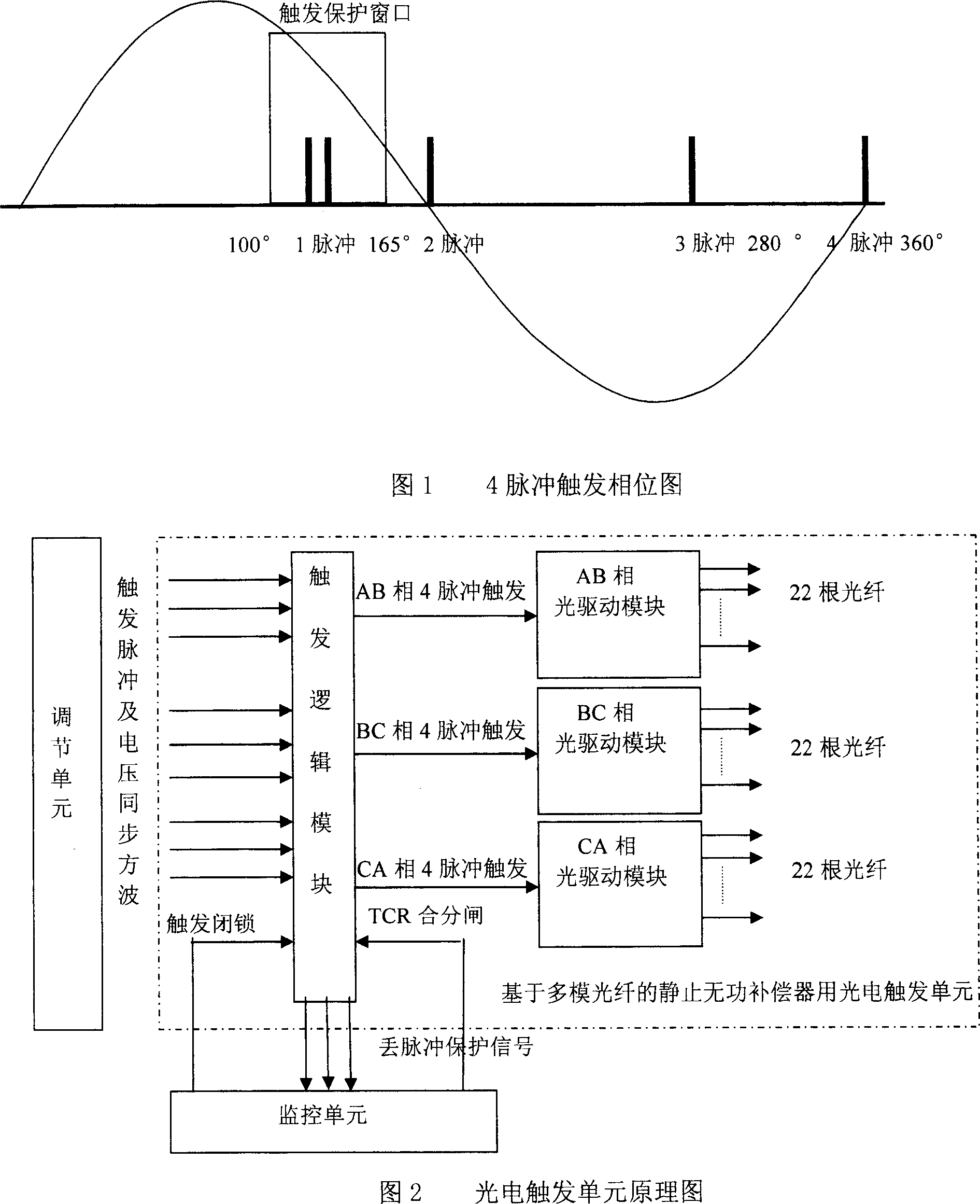
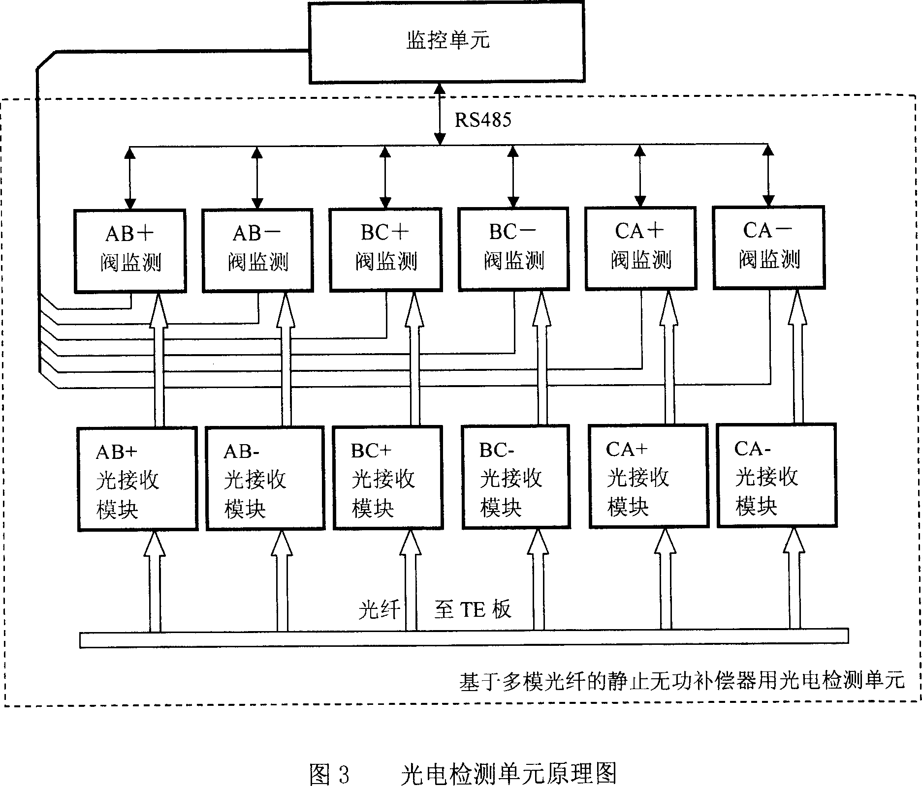
[0030] Referring to accompanying drawings 2 and 3, the photoelectric trigger and detection system based on multimode fiber includes a photoelectric trigger unit and a photoelectric detection unit. The photoelectric trigger unit includes: trigger logic module, AB phase, BC phase, CA phase optical drive module and trigger optical fiber.
[0031] The photoelectric detection unit includes 6 valve detection modules, AB+, AB-, BC+, BC-, CA+, CA-light receiving modules and optical fibers.
[0032] The adjustment unit of the SVC control system obtains the thyristor trigger phase by calculating the three-phase voltage and current of the compensated system, and sends it to the photoelectric trigger unit in the form of a narrow single pulse, which is divided into AB+, AB-, BC+, BC-, CA+, CA - 6 trigger pulses in total. The positive firing angle is between 105° and 165°, and t...
PUM
 Abstract
Description
Claims
Application Information
 - R&D
- Intellectual Property
- Life Sciences
- Materials
- Tech Scout
- Unparalleled Data Quality
- Higher Quality Content
- 60% Fewer Hallucinations
Browse by: Latest US Patents, China's latest patents, Technical Efficacy Thesaurus, Application Domain, Technology Topic, Popular Technical Reports.
© 2025 PatSnap. All rights reserved.Legal|Privacy policy|Modern Slavery Act Transparency Statement|Sitemap|About US| Contact US: help@patsnap.com


