Dust collector roller

A technology of vacuum cleaners and rollers, which is applied to vacuum cleaners, cleaning equipment, household appliances, etc., can solve the problems of insufficient binding force, large impact force, and rotation to prevent the wear of protrusions 72, and achieve the effect of improving binding force.

Inactive Publication Date: 2006-05-10
LG ELECTRONICS (TIANJIN) APPLIANCES CO LTD
View PDF0 Cites 4 Cited by
  • Summary
  • Abstract
  • Description
  • Claims
  • Application Information

AI Technical Summary

Problems solved by technology

[0018] That is, because the binding force between the anti-rotation groove 82 and the anti-rotation protrusion 72 for fixing the inner wheel 80 and the outer wheel 70 is not large enough, the anti-rotation protrusion 72 may be worn or damaged after the vacuum cleaner is used for a long time.
[0019] At this time, as the anti-rotation protrusion 72 is worn or damaged, the binding force between the inner wheel

Method used


Image

  • Dust collector roller
  • Dust collector roller
  • Dust collector roller

Examples


Embodiment Construction

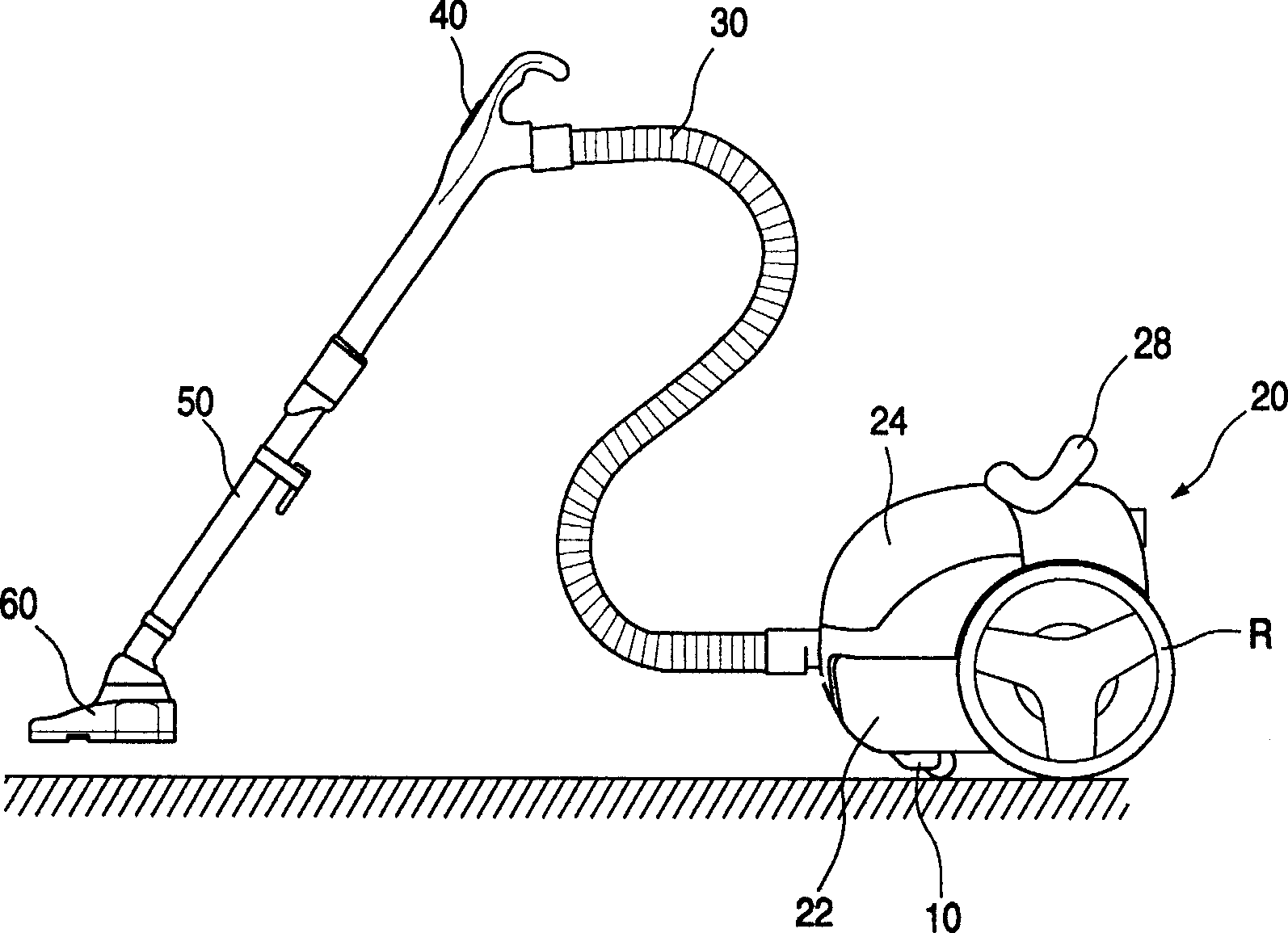
[0065] Figure 4 It is an oblique view of the appearance of the upright vacuum cleaner applying the example of the present invention.

[0066] As shown in the figure, the upright vacuum cleaner is mainly composed of the following parts: a suction nozzle body 100 that moves along the ground and can absorb air containing foreign substances; a body 200 that includes functional components that generate suction for sucking foreign substances and air; Provided on the upper part of the body 200, the user can operate the operating part 210 and the like when using the vacuum cleaner.

[0067] The said nozzle body 100 is a part which sucks in air by the suction port (not shown) provided in the bottom part. That is, the shell of the nozzle body 100 is composed of a nozzle upper shell 110 arranged on the upper side and a nozzle lower shell 120 arranged at the bottom, and the suction nozzle shell 120 should be provided with a suction port of the external air suction passage.

[0068] The...


PUM


Abstract

The invention relates to an idler wheel of vacuum dust-collector which inserts the inner wheel into the casting mould to form the outer wheel without using special combination element, to integrate the inner and outer wheels as a whole. The inventive idler wheel comprises: a lower part to generate suction force; an outer wheel contacting the ground when moving machine body; an inner wheel embedded into the inner side of outer wheel to support the weight of machine body; and a rotational shaft inserted and mounted at the centers of inner and outer wheels with the rotation function. Wherein, the rotational shaft is formed by an anti-drop groove along the periphery with a certain depth to insert the stop ring S; and a friction part beside the anti-drop groove along the periphery with a certain length of projection. Said structure can avoid the slide between the inner and outer wheel and reduce the producing process and cost.

Description

technical field [0001] The present invention relates to a vacuum cleaner, and more specifically to the invention of a vacuum cleaner roller whose rotating shaft is fixed under the simultaneous action of an inner wheel and an outer wheel without using special joint parts. Background technique [0002] first with figure 1 As shown, a brief introduction is made to the existing general vacuum cleaners. As shown in the figure, a general vacuum cleaner is composed of the following parts: a body 20 that contains functional parts (not shown) that can suck in foreign matter on the ground; Suction nozzle 60. [0003] The above-mentioned body 20 is composed of the following parts: the lower body 22 that includes the components (not shown) of the suction function; the upper part that prevents the above-mentioned functional parts included in the lower body 22 from falling out, and includes other hidden parts (not shown) of the vacuum cleaner. Airframe 24. In this way, the appearance ...

Claims


Application Information

Patent Timeline
IPC IPC(8): A47L9/00
Inventor 朴成浩
Owner LG ELECTRONICS (TIANJIN) APPLIANCES CO LTD
Why Eureka
Try Eureka