Heat-pump type hot water supply system

A hot water supply device and heat pump technology, applied in heat pumps, fluid heaters, lighting and heating equipment, etc., can solve problems such as power coefficient drop and increase in pipe pressure loss

Inactive Publication Date: 2006-05-10
PANASONIC CORP
View PDF0 Cites 8 Cited by
  • Summary
  • Abstract
  • Description
  • Claims
  • Application Information

AI Technical Summary

Problems solved by technology

[0003] However, in the above-mentioned conventional device, since the refrigerant tube for heat exchange with the refrigerant supplied from the evaporator to the compressor is provided, there is an increase in the pressure loss inside the refrigerant tube and a power loss. The problem of falling coefficients

Method used


Image

  • Heat-pump type hot water supply system
  • Heat-pump type hot water supply system
  • Heat-pump type hot water supply system

Examples


Embodiment 1

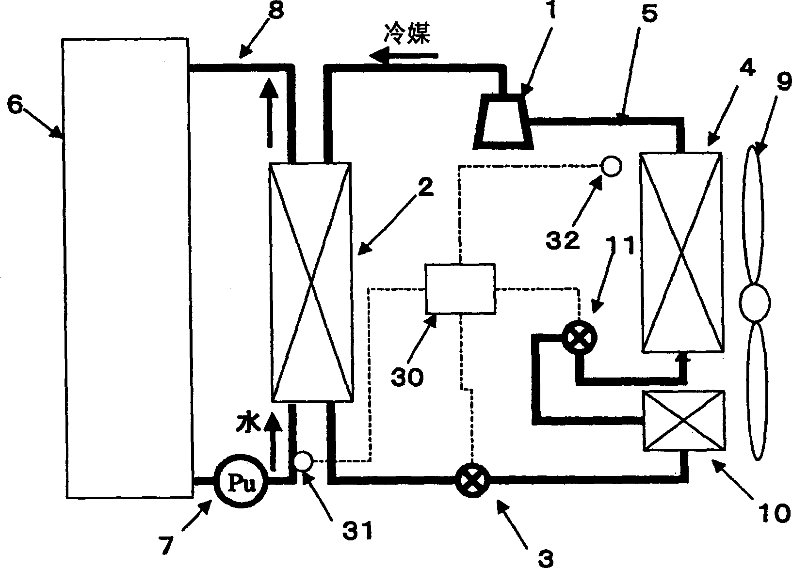
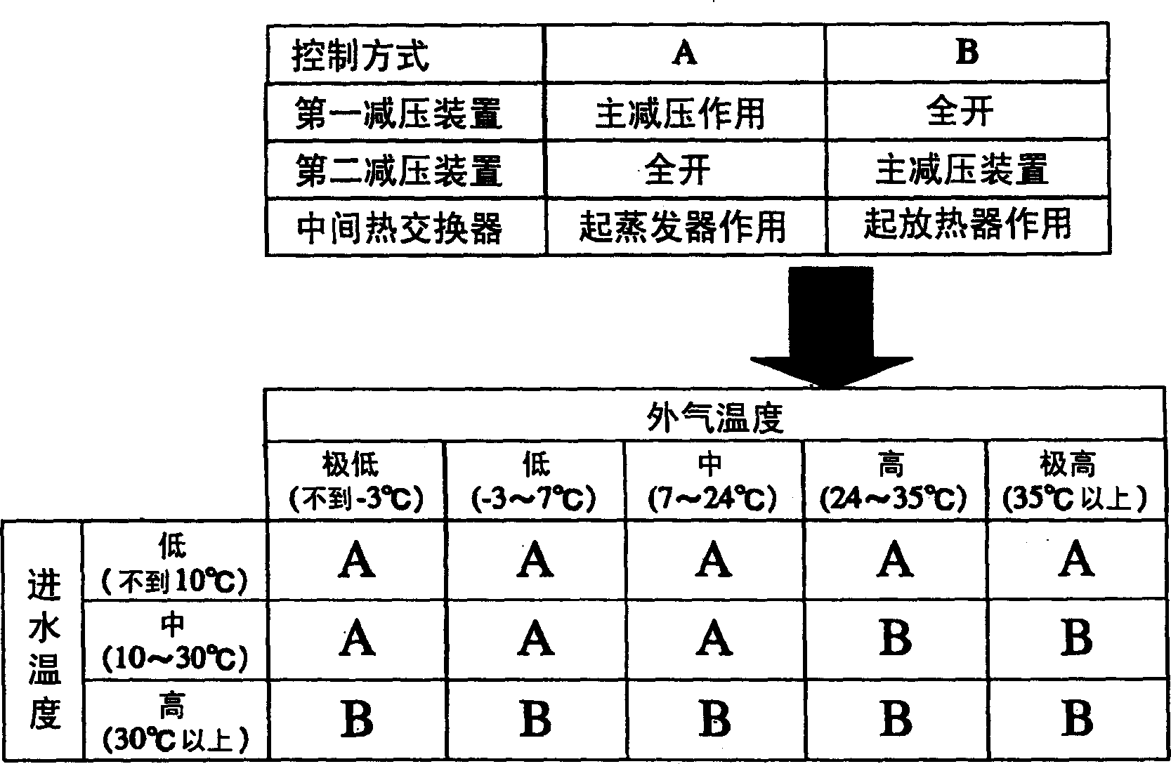
[0018] figure 1 and figure 2 Shown is the heat pump type hot water supply device and its operation control process in the first embodiment of the present invention. Such as figure 1 As shown in , in the heat pump hot water supply device in this embodiment, the compressor 1, the hot water supply radiator 2 for exchanging heat between water and refrigerant, the first decompression device 3, and the refrigerating The intermediate heat exchanger 10 for exchanging heat between the refrigerant and the outside air, the second decompression device 11 and the evaporator 4 for exchanging heat between the refrigerant and the outside air are connected through the refrigerant pipe 5 to form a loop. In addition, the heat pump hot water supply device in this embodiment is also provided with: a heat pump loop that can adjust the valve opening of the decompression device, and a hot water storage tank that stores liquid for hot water supply. 6. A liquid pipeline 8 that can circulate the liq...

Embodiment 2

[0023] In the second embodiment of the present invention, the refrigerant in the heat pump hot water supply device of the first embodiment is replaced with carbon dioxide.

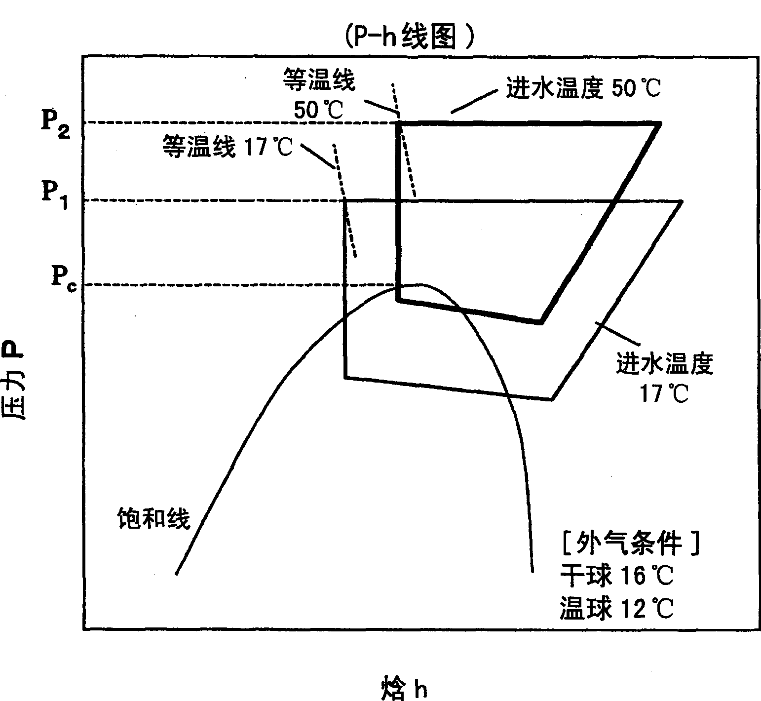
[0024] The function of this embodiment will be described in detail below. image 3 The Mollier diagram (also known as enthalpy-entropy diagram or p-h diagram) when the intermediate heat exchanger acts as an evaporator is shown in , Figure 4 A Mollier diagram in the second embodiment when the intermediate heat exchanger functions as a radiator is shown in . From image 3 It can be seen from the figure that when the above-mentioned intermediate heat exchanger maintains the function of the evaporator, when the inlet water temperature rises from 17°C to 50°C, carbon dioxide will form a supercritical cycle; at this time, according to the isotherm of carbon dioxide, the pressure will become very high and the operation will have to be performed under very high pressure. Thus, the power coefficient of operatio...


PUM


Abstract

The present invention provides a heat pump type hot water supply device, which can suppress the increase of refrigerant pressure and the decrease of power coefficient when the inlet water temperature and the external air temperature become high. This heat pump hot water supply device includes: a compressor (1), a heat radiator (2) for hot water supply that exchanges heat between water and refrigerant, a first decompression device (3), and a The intermediate heat exchanger (10) for exchanging heat between the refrigerant and the external air, the second decompression device (11), and the evaporator for exchanging heat between the refrigerant and the external air are sequentially connected to form a heat pump cycle; detecting means (31) for detecting the inlet water temperature of the heat exchanger for hot water supply; detecting means (32) for detecting the temperature of outside air; and controlling means ( 30). Wherein, the valve opening of the decompression device is adjusted according to the detection value detected by the inlet water temperature detection device and/or the external air temperature detection device.

Description

technical field [0001] The invention relates to a heat pump hot water supply device. Background technique [0002] In the existing heat pump hot water supply device of this type, there is generally a device for separating the refrigerant supplied from the hot water supply heat exchanger to the decompression device and the refrigerant supplied from the evaporator to the compressor. Refrigerant heat exchanger for heat exchange (for an example, refer to Japanese Patent Publication No. 3316444). [0003] However, in the above-mentioned conventional device, since the refrigerant tube for heat exchange with the refrigerant supplied from the evaporator to the compressor is provided, there is an increase in the pressure loss inside the refrigerant tube and a power loss. The problem of falling coefficients. Contents of the invention [0004] The present invention aims to solve the above problems, and its object is to provide a heat pump type hot water supply device capable of sup...

Claims


Application Information

Patent Timeline
Patent Type & Authority Applications(China)
IPC IPC(8): F24H4/04F24H9/20
CPCF25B6/04F25B30/02F25B2309/061F25B2339/047F25B2700/2106F25B2700/21161F25B41/39F25B41/34Y02B30/70
Inventor 渡部安司
Owner PANASONIC CORP
Why Eureka
Try Eureka