Cpp-type giant manetoresistance effect element and magnetic component and magnetic device using it

A giant magnetoresistance element and magnetic technology, applied in the field of giant magnetoresistance effect elements, magnetic components and magnetic devices, can solve the problem of small resistance change ΔR and magnetoresistance change rate, small current path of CPP-GMR element, and hindrance of CPP-GMR Issues such as component availability

Inactive Publication Date: 2006-05-10
JAPAN SCI & TECH CORP
View PDF3 Cites 4 Cited by
  • Summary
  • Abstract
  • Description
  • Claims
  • Application Information

AI Technical Summary

Problems solved by technology

[0007] However, the CPP-GMR element has not been put into practical use because the current path is small and the resistance is small, the element size is not quite small, and it is not practical.
[0008] Also discussed in CPP-GMR elements such as Figure 10 As shown, the antiferromagnetic layer 81 is close to the spin valve type of the ferromagnetic pinned layer 82, but compared with the GMR film composed of the ferromagnetic free layer 84/nonmagnetic conductive layer 83/ferrom

Method used


Image

  • Cpp-type giant manetoresistance effect element and magnetic component and magnetic device using it
  • Cpp-type giant manetoresistance effect element and magnetic component and magnetic device using it
  • Cpp-type giant manetoresistance effect element and magnetic component and magnetic device using it

Examples


Embodiment Construction

[0049] Below, according to Figure 1 ~ Figure 1 9 to describe in detail the best implementation of the present invention. In the drawings, the same symbols are used for the same or corresponding parts.

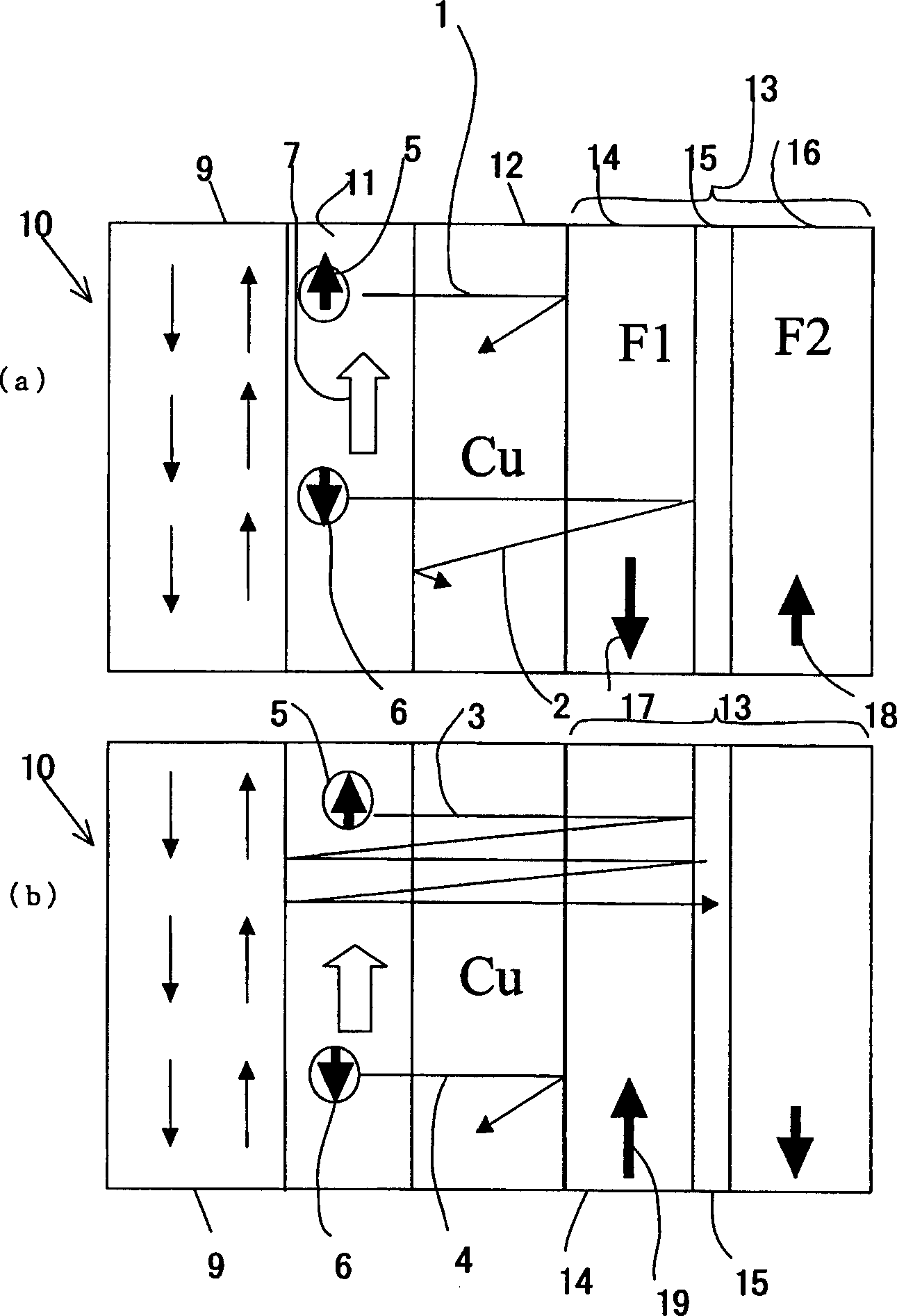
[0050] figure 1 It is a conceptual diagram of the valve-type CPP giant magnetoresistance element of the first embodiment, figure 1 (a) is the case where the magnetization of the first magnetic layer of the ferromagnetic free layer is antiparallel to the magnetization of the pinned layer, figure 1 (b) shows the case of parallelism. Such as figure 1 As shown, the CPP type giant magnetoresistive element 10 of the first embodiment is formed as follows: the antiferromagnetic layer 9, the ferromagnetic fixed layer 11, the nonmagnetic conductive layer 12 and the ferromagnetic free layer 13 have a laminated structure, and the ferromagnetic free layer The first magnetic layer 14 and the second magnetic layer 16 of 13 are magnetically antiparallel coupled through the magnetic c...


PUM

PropertyMeasurementUnit
Film thicknessaaaaaaaaaa

Abstract

CPP-type giant magnetoresistance elements, magnetic components and magnetic devices can exhibit giant magnetoresistance effects through spin-related currents in the vertical direction of the film surface, wherein the CPP-type giant magnetoresistance elements (10, 20, 50) have antiferromagnetic layers (9), laminated structure of ferromagnetic fixed layer (11, 11A), non-magnetic conductive layer (12) and ferromagnetic free layer (13, 13A), the first magnetic layer of ferromagnetic free layer (13, 13A) (14, 14A) and the second magnetic layer (16, 16A) are magnetically antiparallel coupled through a magnetic coupler (15, 15A), and the magnetization (17, 17') of the first magnetic layer (14, 14A) is connected to the first magnetic layer (14, 14A). 2 Magnetizations (18, 18A) of the magnetic layers (16, 16A) are different in magnitude. Up-spinning electrons (5) and down-spinning electrons (6) are spin-dependently scattered according to the magnetization directions of the ferromagnetic pinned layer (11, 11A) and the ferromagnetic free layer (13, 13A), and the CPP-GMR passes through the conduction channel (1 , 2, 3, 4) and increase. In addition, in the CPP type giant magnetoresistance element (30) with ferromagnetic pinned layer (11), nonmagnetic conductive layer (12) and ferromagnetic free layer (13A), between ferromagnetic pinned layer (11) and nonmagnetic Between the conductive layers (12) and/or on the surface of the ferromagnetic free layer (13A), a layer (21) formed of one or not less than two of ruthenium, iridium, rhodium, rhenium, and chromium is provided.

Description

technical field [0001] The invention relates to a giant magnetoresistance effect element (hereinafter referred to as a CPP type giant magnetoresistance effect element) and a magnetic component and a magnetic device using the giant magnetoresistance effect element, which can exhibit giant magnetoresistance through a spin-related current in a vertical direction of the film surface effect. Background technique [0002] In recent years, a giant magnetoresistance (GMR) effect element composed of a ferromagnetic layer / nonmagnetic metal layer / ferromagnetic layer is being developed. GMR is caused by spin-dependent scattering at the interface, and the magnetization of the two ferromagnetic layers is controlled to be parallel or antiparallel to each other by an external magnetic field, so that their resistances are different from each other. [0003] GMR elements have been applied to magnetic sensors, reproduction heads of hard disk devices, and the like. In this case, the current f...

Claims


Application Information

Patent Timeline
IPC IPC(8): H01L43/08G01R33/09G11B5/39H01L27/105
Inventor 猪俣浩一郎手束展规
Owner JAPAN SCI & TECH CORP
Why Eureka
Try Eureka