
Organic light-emitting device

A technology of organic light-emitting devices and light-emitting layers, which can be used in light-emitting materials, household components, applications, etc., and can solve the problems of low efficiency and short life of fluorescent devices

Active Publication Date: 2006-05-17
SAMSUNG DISPLAY CO LTD
View PDF0 Cites 24 Cited by
  • Summary
  • Abstract
  • Description
  • Claims
  • Application Information

AI Technical Summary

Problems solved by technology

[0006] However, when conventional carbazole-based compounds are used, fluorescent devices have low efficiency and short lifespan, so there is still much room for improvement in fluorescent devices.

Method used


Image

  • Organic light-emitting device
  • Organic light-emitting device
  • Organic light-emitting device

Examples


example 1

[0064] In order to prepare the anode, 15Ω / cm 2 (1200) ITO glass substrate (Corning Inc.) was cut into a size of 50mm×50mm×0.7mm, and then the cut glass substrate was cleaned in isopropanol and deionized water with ultrasonic waves for five minutes. Then, The cleaned glass substrate was exposed to ultraviolet rays and ozone for thirty minutes.

[0065] Then, N,N'-bis(1-naphthyl)-N,N'-diphenylbenzidine (NPD) was vacuum deposited on the substrate to form a hole transport layer with a thickness of 600 angstroms.

[0066] 100 parts by weight of the host material, 90 parts by weight of CBP and 10 parts by weight of dmCBP and 100 parts by weight of the light-emitting layer, 5 parts by weight of Ir( ppy) 3 It was vacuum deposited on the hole transport layer to form a 400 Å light emitting layer.

[0067] Alq3 is deposited on the light-emitting layer to form an electron transport layer with a thickness of 300 Å.

[0068] An electron injection layer with a thickness of 10 Å containing LiF a...

example 2

[0070] Except that 75 parts by weight of CBP and 25 parts by weight of dmCBP were used to form the light-emitting layer, the same method as in Example 1 was used to construct a light-emitting device.

example 3

[0072] The same method as in Example 1 was used to construct a light emitting device except that 50 parts by weight of CBP and 50 parts by weight of dmCBP were used to form the light-emitting layer.


PUM

PropertyMeasurementUnit
Emission efficiencyaaaaaaaaaa

Abstract

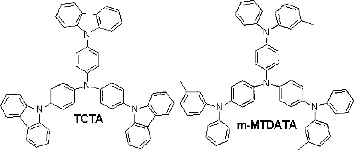
The present invention provides an organic glowing device.The organic light emitting device includes the first electrode, the second electrode, and the light layer between the first electrode and the second electrode.The device also contains fluorescent doping agents and fluorescent main body containing at least two kinds of cave transmission materials.The mixed fluorescent main material improves energy migration efficiency, thereby improving the efficiency and life of the organic lighting device obtained.

Description

Technical field [0001] The invention relates to an organic light-emitting device in which at least two hole transport materials are used as a fluorescent host, thereby improving the efficiency and life of the device. Background technique [0002] The light-emitting materials used in organic light-emitting devices are classified into fluorescent materials using singlet excitons and fluorescent materials using triplet excitons, where the two materials have different emission mechanisms. [0003] Generally, the fluorescent material contains an organometallic compound containing heavy atoms. In fluorescent materials, excitons transition from a triplet state to a singlet state, thereby emitting light. The fluorescent material may use triplet excitons constituting 75% of excitons, thereby having a higher emission efficiency than a fluorescent material using singlet excitons constituting the remaining 25% of excitons. [0004] The light-emitting layer containing...

Claims


Application Information

Patent Timeline
IPC IPC(8): H01L51/50C09K11/06H01L51/54
CPCC09K11/06Y10S428/917H10K50/171H10K50/18H10K50/16H10K50/15H10K50/17H10K50/11
Inventor 李俊烨千民承崔镕中
Owner SAMSUNG DISPLAY CO LTD
Learn More