Timing belt

A timing belt and belt body technology, applied in the direction of transmission belts, belts/chains/gears, mechanical equipment, etc., can solve problems such as difficult reinforcement methods, and achieve the effects of enhancing rigidity, reducing wear, and preventing longitudinal tearing

Inactive Publication Date: 2006-05-24
HONDA MOTOR CO LTD
View PDF0 Cites 10 Cited by
  • Summary
  • Abstract
  • Description
  • Claims
  • Application Information

AI Technical Summary

Problems solved by technology

[0007] However, it is difficult to say that the conventional reinforcement method is necessary and sufficient for the timing belt whose usage conditions have become severe in recent years

Method used


Image

  • Timing belt
  • Timing belt
  • Timing belt

Examples


Embodiment Construction

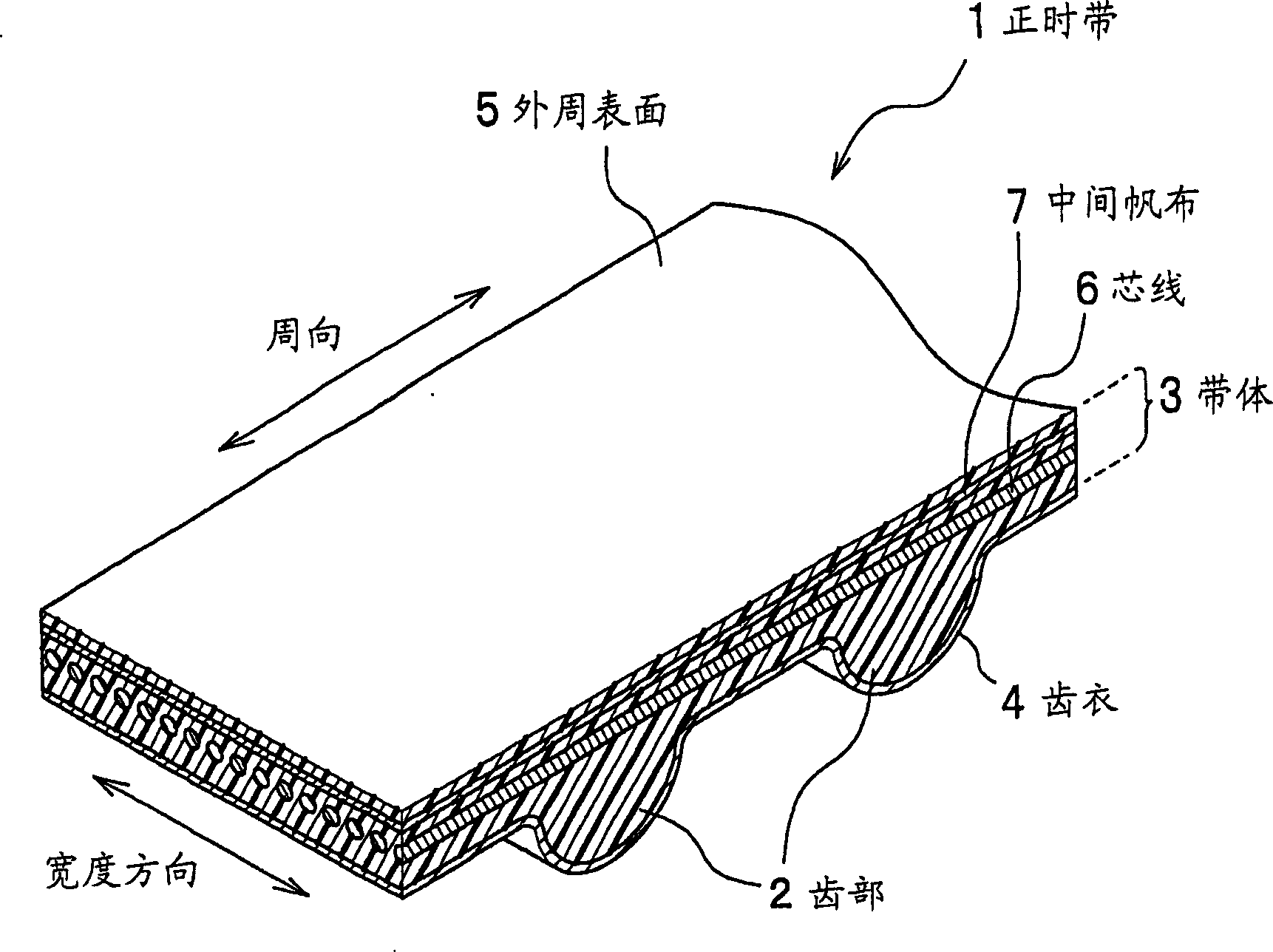
[0028] The best mode for carrying out the present invention will be described in detail below with reference to the appropriate drawings. figure 1 It is a cross-sectional perspective view showing a part of the timing belt of this embodiment. Since the timing belt is generally used in severe environments where the timing belt is liable to deteriorate, such as an increase in ambient temperature and contact with engine oil and cooling water, durability that can withstand these environments is required.

[0029] Such as figure 1 As shown, the timing belt 1 includes: an endless belt body 3; a plurality of tooth portions 2 formed at predetermined intervals along the inner peripheral surface of the belt body 3; a tooth coat 4 covering the surface of the tooth portion 2; The core wire 6 embedded in the circumferential direction; and the intermediate canvas 7 provided on the outer peripheral side of the core wire 6 in the belt body 3 .

[0030] The setting of the middle canvas 7 to b...


PUM


Abstract

The object of the present invention is to provide a timing belt capable of reinforcing the tensile rigidity of the belt, preventing local deflection of the core wire due to polygonal engagement by adjusting the flexibility on the outer peripheral side of the pitch wire, and improving the timing belt. resistance to flex fatigue. The timing belt (1) includes: an endless belt body (3); a plurality of teeth (2) formed at predetermined intervals along the inner peripheral surface of the belt body (3); The core wire (6); and the intermediate canvas (7) arranged on the outer peripheral side of the core wire (6) in the belt body (3), wherein the intermediate canvas (7) has stretchability along the circumferential direction.

Description

technical field [0001] The invention relates to a timing belt for synchronous transmission. Background technique [0002] The timing belt is a belt on which teeth are formed at predetermined intervals in the circumferential direction on the inner peripheral side of an endless belt body, and is suitable for applications requiring synchronous rotation. Although examples of methods for accurately transmitting rotational motion include gears and chains, timing belts have advantages such as low noise, no need for oil supply, and small transmission errors. [0003] For example, a timing belt is used as a belt for synchronizing the crankshaft and cams of an automobile engine. In addition, timing belts can be used in all belt drive systems that require synchronous transmission, such as precision instruments such as cameras, computers and copiers, and general industrial equipment. [0004] In particular, a timing belt for transmitting power to various parts of an automobile engine ...

Claims


Application Information

Patent Timeline
Patent Type & Authority Applications(China)
IPC IPC(8): F16G1/10F16G1/28
CPCF16G1/28
Inventor 嶋村馨
Owner HONDA MOTOR CO LTD
Why Eureka
Try Eureka