Controllable damp device of ferromagnetic resonance for electromagnetic voltage transformer for distribution network

A technology of voltage transformer and ferromagnetic resonance, which is applied in circuit devices, emergency protection circuit devices, electrical components, etc., and can solve problems such as blown high-voltage fuses and burned PTs of weakly insulated equipment

Inactive Publication Date: 2006-05-24
NORTH CHINA ELECTRIC POWER UNIV (BAODING)
View PDF0 Cites 16 Cited by
  • Summary
  • Abstract
  • Description
  • Claims
  • Application Information

AI Technical Summary

Problems solved by technology

The system bus is connected with an electromagnetic voltage transformer (PT) for measuring and monitoring the insulation to the ground. When the bus switch closes, the single-phase arc of the line disappears automatically, or the system load changes drastically, the temporary The state impact process may excite the ferromagnetic resonance phenomenon between the PT and the capacitance of the three-phase wires to the ground, resulting in system overvoltage and overcurrent in the PT, causing flashover to the ground of the weakly insulated equipment in the system, and blowing of the high voltage fuse of the PT , and even burned PT

Method used


Image

  • Controllable damp device of ferromagnetic resonance for electromagnetic voltage transformer for distribution network
  • Controllable damp device of ferromagnetic resonance for electromagnetic voltage transformer for distribution network
  • Controllable damp device of ferromagnetic resonance for electromagnetic voltage transformer for distribution network

Examples


Embodiment Construction

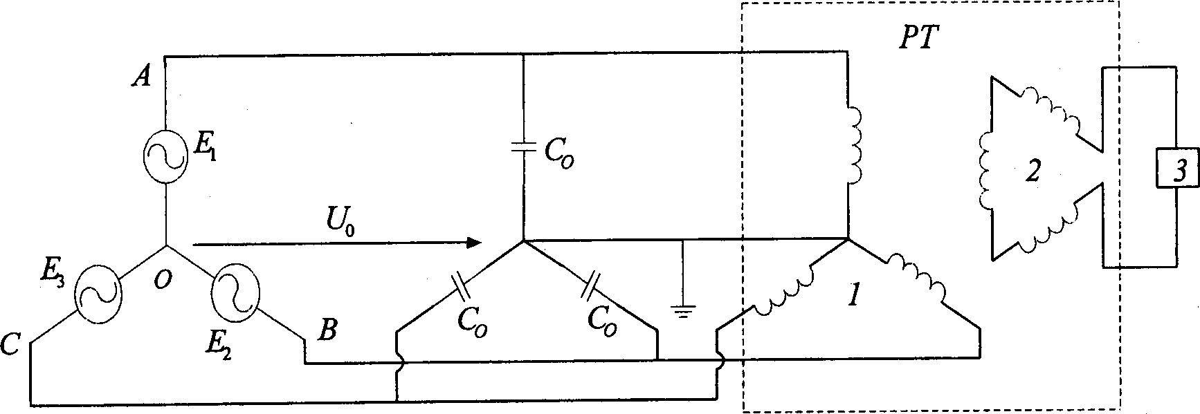
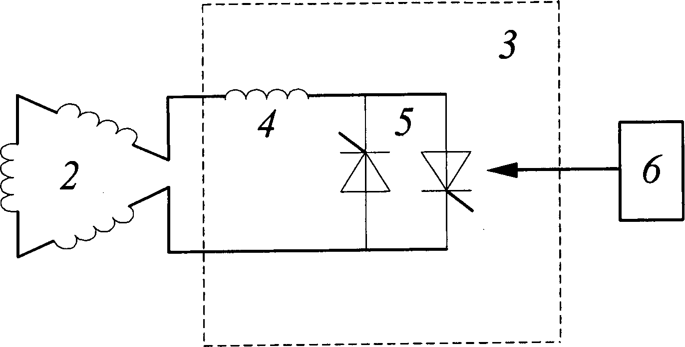
[0014] Figures 1 to 4 are A specific embodiment of the present invention. The main circuit of the controllable damping device is two thyristor elements 5 connected in anti-parallel and then a damping reactor 4 in series to form a main circuit 3 with a topological structure of thyristor-controlled reactors. Both ends of the main circuit 3 are connected to the PT secondary The two ends of the side opening triangular winding 2. Controller 6 uses 89C51 single-chip microcomputer as the control core, and AD574 implements the measurement of the zero-sequence voltage of the port of the PT open triangle winding, and generates a trigger pulse through the P1 port of 89C51, and the pulse passes through the photoelectric isolation device, Darlington power drive circuit and pulse transformer Finally, the gate triggering of the two anti-parallel thyristors 5 in the main circuit of the device is implemented. The controller 6 sends or blocks the trigger pulse to control the turn-on and natu...


PUM


Abstract

Belonging to technical field of control and protection, the controllable damping device includes damping reactor, inverse parallel controllable silicon, triggering controller. Damping reactor and inverse parallel controllable silicon are cascaded to constitute a damping control main circuit, which is connected to port of triangle winding at opening of PT secondary side. Advantages are that the invention can distinguish resonance fault from singlephase earth fault to implement correct damping control of resonance as well as indicate which fault including faults of frequency division, basic frequency, ferro resonance in high frequency and single phase grounding occurs in system correctly. The device does not influence on normal operation of electric network and collection of system zero sequence signal, does not generate higher harmonic and other interference signal.

Description

technical field [0001] The invention belongs to the technical field of distribution network control and protection, and in particular provides a controllable damping device for ferromagnetic resonance of an electromagnetic voltage transformer of a distribution network. Background technique [0002] In the distribution network of 6 ~ 35kV, the neutral point of the system is generally not grounded. The system bus is connected with an electromagnetic voltage transformer (PT) for measuring and monitoring the insulation to the ground. When the bus switch closes, the single-phase arc of the line disappears automatically, or the system load changes drastically, the temporary The state impact process may excite the ferromagnetic resonance phenomenon between the PT and the capacitance of the three-phase wires to the ground, resulting in system overvoltage and overcurrent in the PT, causing flashover to the ground of the weakly insulated equipment in the system, and blowing of the hig...

Claims


Application Information

Patent Timeline
Patent Type & Authority Applications(China)
IPC IPC(8): H02H7/05H02J3/00
Inventor 尹忠东
Owner NORTH CHINA ELECTRIC POWER UNIV (BAODING)
Why Eureka
Try Eureka