Active superconducting direct current limiter

A technology of current limiter and current limiter, which is applied in the usage of superconductor elements, emergency protection circuit devices for limiting overcurrent/overvoltage, electrical components, etc., which can solve the problems of large loss and affecting system economy, etc. Achieve the effect of improving safety stability and ensuring dynamic response characteristics

Inactive Publication Date: 2006-05-24
HUAZHONG UNIV OF SCI & TECH
View PDF1 Cites 3 Cited by
  • Summary
  • Abstract
  • Description
  • Claims
  • Application Information

AI Technical Summary

Problems solved by technology

The current limiter uses a voltage source connected in series with a resistor to provide a bias current, which will generate a certain resistance loss during operation, which is proportional to the square of the current. When the operating current level of the DC system is high, the bias The loss generated by the source will be very large, which will affect the economy of the system operation

Method used


Image

  • Active superconducting direct current limiter
  • Active superconducting direct current limiter
  • Active superconducting direct current limiter

Examples


Embodiment Construction

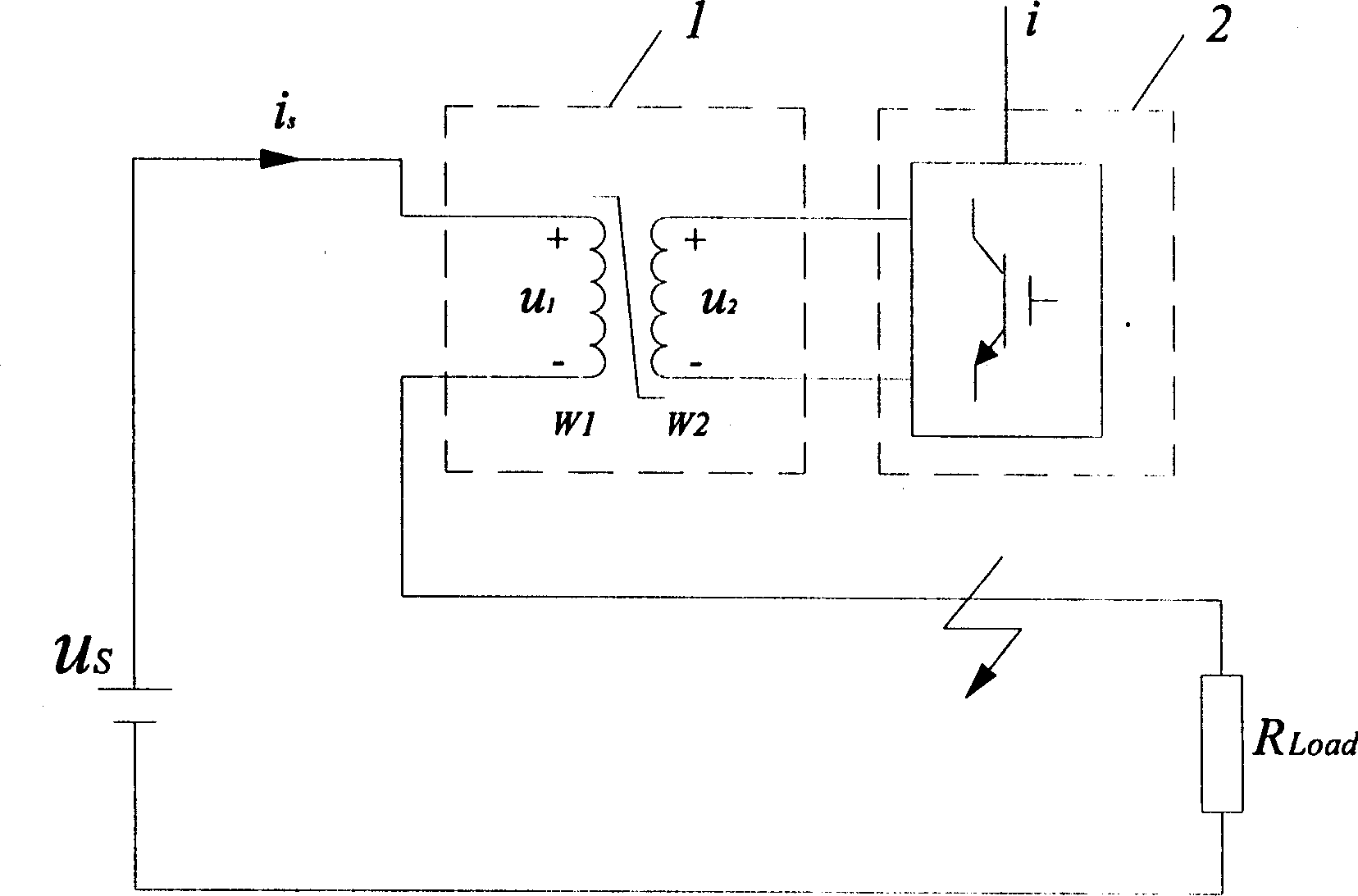
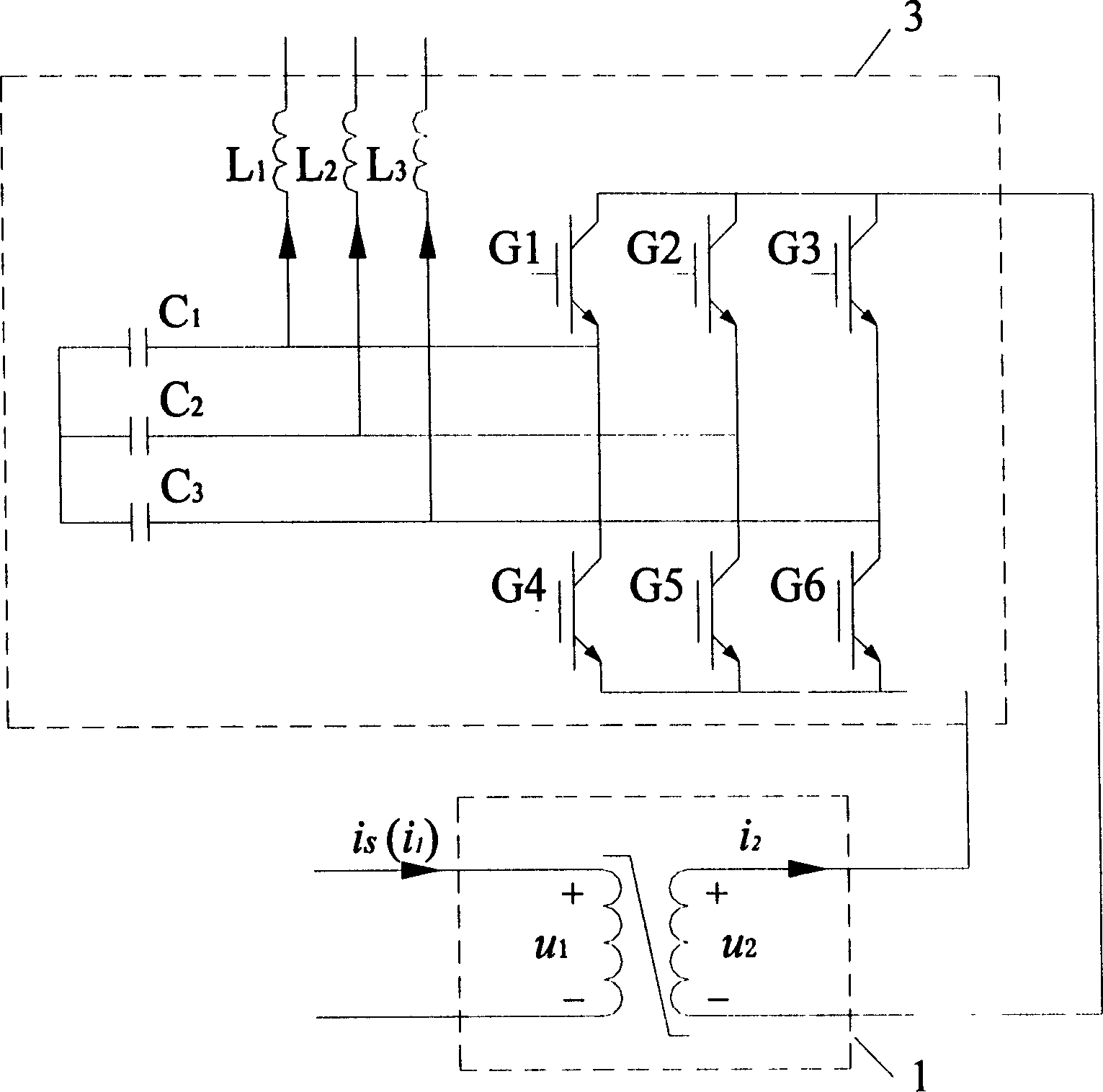
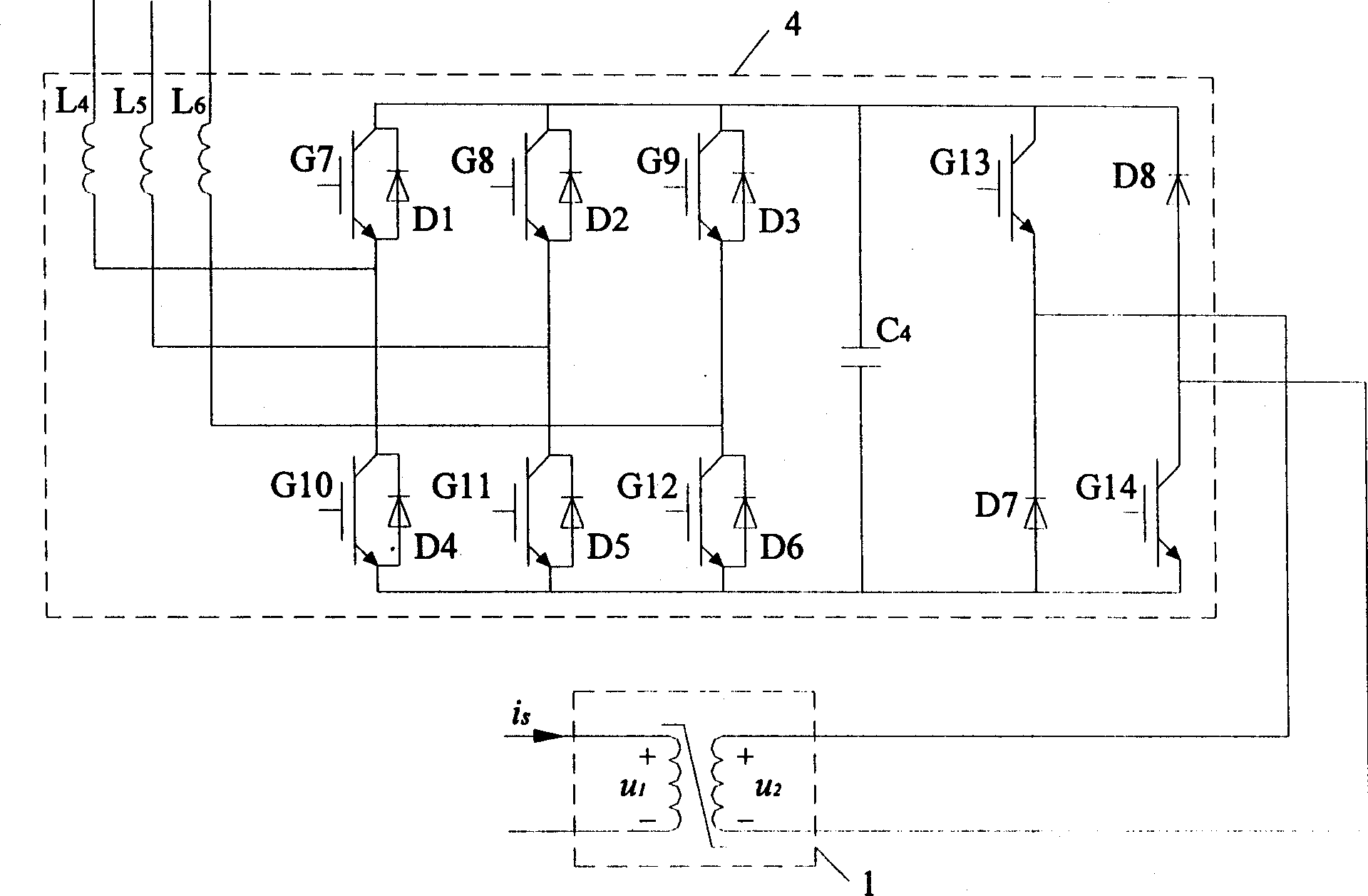
[0024] Depend on figure 1 As shown, the active superconducting DC current limiter of the present invention includes a superconducting transformer 1 and a PWM converter 2. The structure of the superconducting transformer 1 is that two superconducting coils W1 and W2 are wound on the iron core, and the primary side superconducting coils W1 and W2 are wound on the iron core. The conducting coil W1 is connected to the DC system in series, the secondary side superconducting coil W2 is connected to the AC system through the PWM converter 2, the iron core of the superconducting transformer 1 works in the linear region, and the secondary side superconducting coil W2 is connected to the AC system. The active power is released to limit the short-circuit current of the DC system. u s is the equivalent voltage source of the DC system, R Load is the equivalent load resistance of the DC system. According to the different materials used for the superconducting coil, the superconducting tr...


PUM


Abstract

The current limiter includes superconducting transformer, and PWM converter. Structure of the superconducting transformer is as following: two superconducting windings W1, W2 are prepared on iron core; winding W1 at primary side is cascaded to DC system. Through PWM converter, winding W2 at secondary side is connected to AC system. Through winding W2, iron core working at range of linearity releases active power to AC system to restrict short circuit current of DC system. When DC system operates normally, or short trouble occurs, PWM converter can make quick response to wattless requirement for AC system in order to provide voltage support for AC system. The current limiter can carry out dynamic reactive compensation for connected AC electrical power system. The invention raises safety stability of operation of AC electrical power system. The invention is applicable to DC power system and DC transmission system in high voltage in ship.

Description

technical field [0001] The invention is a short-circuit current limiting protection device of a DC power system. Background technique [0002] In order to limit the short-circuit current, the usual method is to install a DC circuit breaker. When the system fails, the circuit breaker cuts off the short-circuit current to achieve the purpose of fault protection. At present, the DC circuit breaker mainly includes a conversion circuit and an AC circuit breaker. After the fault is short-circuited, an artificial current zero point is generated through the conversion circuit, and then the AC circuit breaker is used to disconnect the short-circuit current. Since the conversion circuit of the circuit breaker needs to detect the short-circuit signal before it can act, the response time of the circuit breaker is long, which is not conducive to the rapid protection of the power system; During fault protection, overvoltage will occur, and the circuit breaker also has disadvantages such ...

Claims


Application Information

Patent Timeline
Patent Type & Authority Applications(China)
IPC IPC(8): H02H9/02H02J3/18
CPCY02E40/30Y02E40/60
Inventor 唐跃进石晶
Owner HUAZHONG UNIV OF SCI & TECH
Why Eureka
Try Eureka