Container checking system with CT fault scanning function

A tomographic scanning and inspection system technology, applied in the direction of measuring devices, nuclear radiation exploration, instruments, etc., can solve the problems of restricting the accuracy of complex container cargo inspection and the inability to obtain tomographic images, so as to achieve reasonable design, accurate inspection results, The effect of reducing the footprint

Active Publication Date: 2006-05-31
NUCTECH CO LTD
View PDF1 Cites 18 Cited by
  • Summary
  • Abstract
  • Description
  • Claims
  • Application Information

AI Technical Summary

Problems solved by technology

[0003] The above-mentioned X-ray radiation imaging inspection system currently in use, because its detection devices are all fixedly installed, usually has only one direction of relative movement with respect to the object to be inspected, so only radiation projection images can be obtained, and the tomography of a certain part of the object to be inspected cannot be obtained. images, which to some extent limits the accuracy of complex cargo inspections

Method used


Image

  • Container checking system with CT fault scanning function
  • Container checking system with CT fault scanning function

Examples


Embodiment Construction

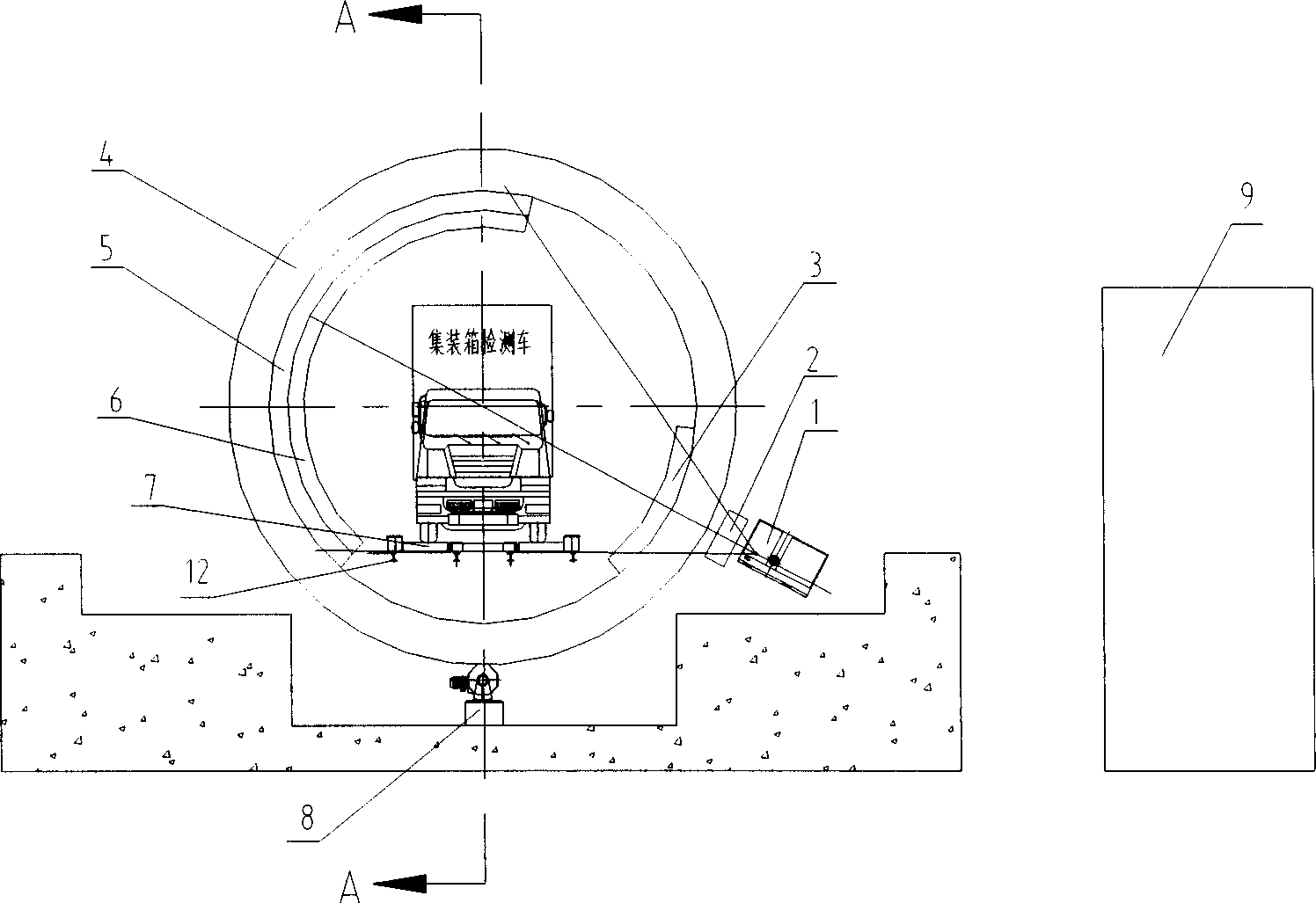
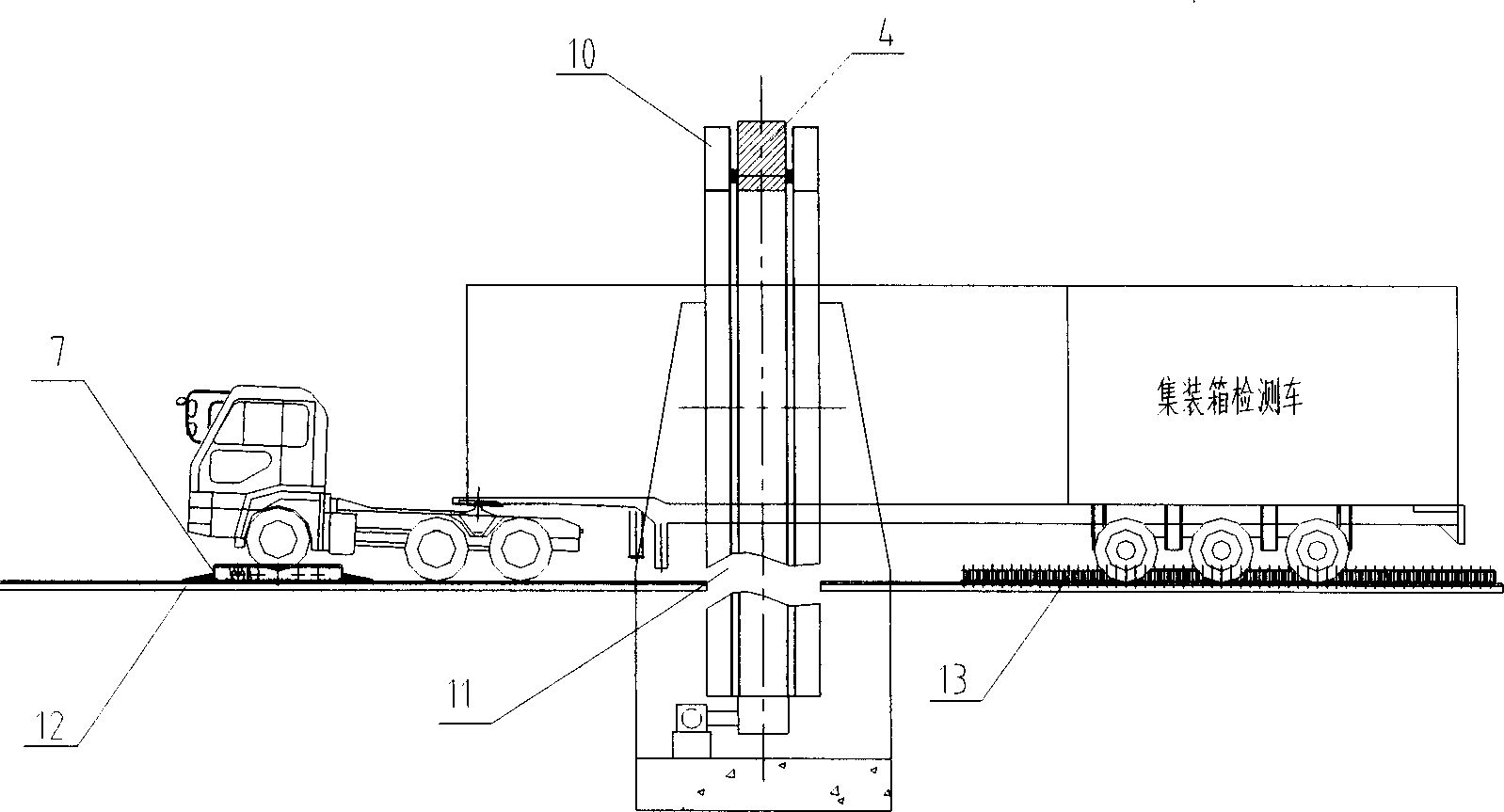
[0014] see figure 1 and figure 2 , the present invention includes a radiation source 1 using a linear electron accelerator or an isotope, a corrector 2, a front collimator 3, a rear collimator 6, a detector array 5 and a rail 12 placed in the scanning area, placed on the rail 12 The trailer 7, the side guide device 13 with a double-sided vertical roller structure placed on the rail 12, and the remote control device 9 equipped with an image acquisition module, an operation inspection module, and an electrical control module. The rail 12 placed in the scanning area is composed of two sections and forms a discontinuous structure, and an annular rotating frame 4 that allows the container inspection vehicle to pass is arranged in the longitudinal direction of the discontinuous gap 11 . The outer side of the circular rotating frame 4 fixes the radiation source 1 and the corrector 2 facing the radiation source 1, and the inner side of the circular rotating frame 4 fixes the front c...


PUM


Abstract

A container detection system with CT fault scan is prepared as fixing radiation source and calibrator facing to said source on external side of circular rotation frame and front collimator, back collimator and detector array on internal side of circular rotation frame to let sector X ray pass through appliance, front collimator and container detection vehicle then to face just to back collimator and detector array; hinging circular rotation frame on circumnavigation frame fixed on ground to enable circular rotation frame to rotate synchronously around a fixed center by utilizing a driving device.

Description

technical field [0001] The invention relates to a large-scale container inspection system used by customs, in particular to a container inspection system capable of CT tomographic scanning. Background technique [0002] In the prior art, since the beginning of the 1990s, drag-type container detection systems have come out, such as the large-scale container detection systems produced by Heyman and British Aerospace. They are installed in a radiation-shielding inspection channel, equipped with a fixed radiation source that can generate high-energy X-rays and an array detector that can receive X-rays passing through the container. The container vehicle is dragged through the detection channel. When the container passes through the X-ray beam, the X-rays that pass through the container penetrate into the detector. According to the intensity change, the density distribution of the objects contained in the box is reflected, and the ray intensity is transformed into The gray scale...

Claims


Application Information

Patent Timeline
Patent Type & Authority Applications(China)
IPC IPC(8): G01N23/04G01N23/083G01N23/10G01V5/00
CPCG01N23/046G01N2223/643G01V5/005G01N2223/419G01V5/0008
Inventor 胡海峰王利明吴玉成孙尚民韩彦军彭华江南梁志忠
Owner NUCTECH CO LTD
Why Eureka
Try Eureka