Shared pixel displaying method

A display method and shared technology, applied in the field of image display technology, can solve the problems of increased cost, high unit cost of driver ICs, and crowded driver IC supply and demand, and achieve the effect of reducing the number, reducing the cost of driving ICs, and reducing image pixels.

Inactive Publication Date: 2006-05-31
SITRONIX TECH CORP
View PDF0 Cites 10 Cited by
  • Summary
  • Abstract
  • Description
  • Claims
  • Application Information

AI Technical Summary

Problems solved by technology

However, for small-sized liquid crystal displays with fixed graphics or text, for driver ICs that account for a very high proportion of LCD cost, each display requires so many driver ICs, which will lead to an increase in cost and cause a gap in the supply and demand of driver ICs. Mutual exclusion, when the demand is more, the unit cost of the driver IC will be higher

Method used


Image

  • Shared pixel displaying method
  • Shared pixel displaying method
  • Shared pixel displaying method

Examples


Embodiment Construction

[0018] Relevant detailed content and technical description of the present invention, now in conjunction with accompanying drawing, explain as follows:

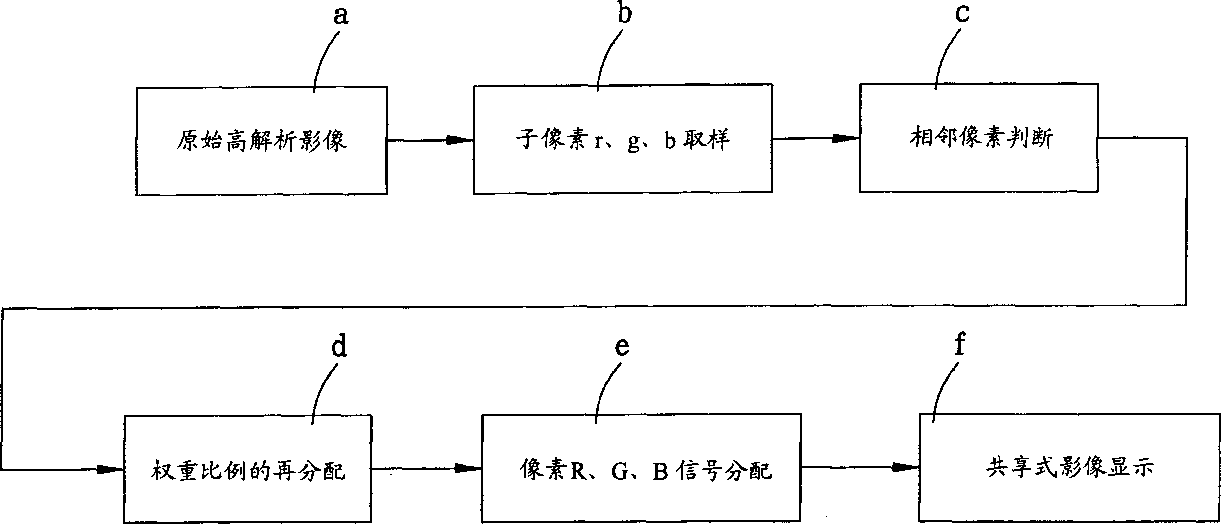
[0019] Please see first figure 2 Shown is a block diagram of the shared pixel display method of the present invention. As shown in the figure, the method mainly includes:

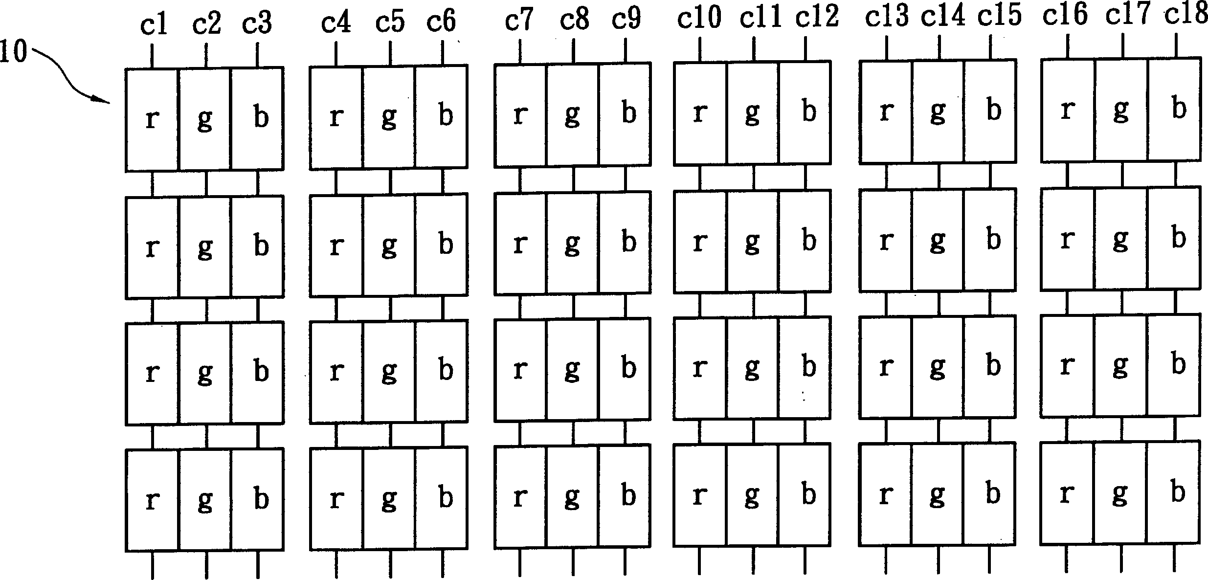
[0020] (a), the original pixels 10 of the original high-resolution image are arranged in a line-stripe shape (such as figure 1 shown).

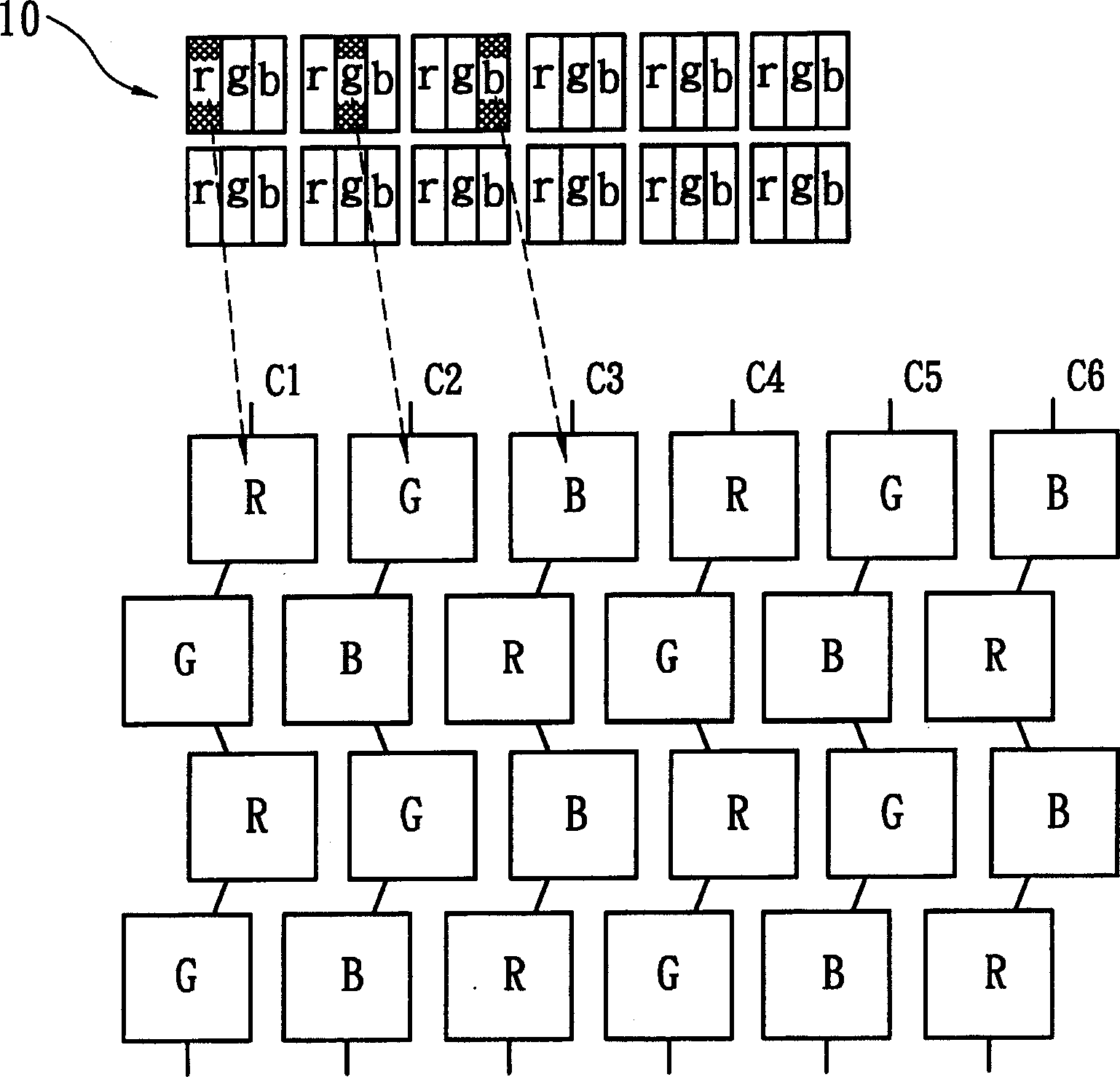
[0021] (b) The original pixel 10 includes sub-pixels r, g, and b. The image display method of converting high resolution to low resolution is aimed at the original pixel 10 displaying the original high-resolution image. The driver IC first controls the sub-pixel r of the original pixel 10 , g, b sampling, the sub-pixel r, g, b sampling is arranged with the pixels R, G, B of the color filter.

[0022] Wherein, the sampling rule is that when the matching color filter is displayed as pixel R, then the sampling of the ori...


PUM


Abstract

A method for displaying shared pixel includes arranging pixel arrangement A of color filter on sub pixel then judging inclusion D ¿C value of sampled adjacent pixel, using adjacent pixel with the same color to carry out weight ratio redistribution and then distributing sampled and weight ¿C ratio redistributed pixel signal to color filter for displaying by driving IC.

Description

technical field [0001] The invention relates to a shared pixel display method, in particular to an image display technology for switching from high resolution to low resolution, so as to reduce the number of driving ICs required by the display. Background technique [0002] Vision is the sensation in the human brain caused by light of different wavelengths acting on the retina, and color vision is the basic function of the visual system, which is of great significance for the detection of images and objects. The wavelength of visible light to the human eye is 390-780 nanometers (nm), and generally 120-180 different colors including 7 main colors of purple, blue, blue, green, yellow, orange and red can be distinguished. Distinguishing colors is mainly the function of visual cells. Because visual cells are concentrated in the center of the retina, the ability to distinguish colors is the strongest there, and approaching the peripheral part, the retina's sensitivity to green, r...

Claims


Application Information

Patent Timeline
Patent Type & Authority Applications(China)
IPC IPC(8): G02F1/133G09F9/00G09G3/36
Inventor 钱金维王秀东
Owner SITRONIX TECH CORP
Why Eureka
Try Eureka