

Industrial robot
A technology of industrial robots and robots, applied in the direction of instruments, manipulators, manufacturing tools, etc., can solve the problems that robots cannot be operated properly
- Summary
- Abstract
- Description
- Claims
- Application Information
AI Technical Summary
Problems solved by technology
Method used
Image

Examples
Embodiment 1
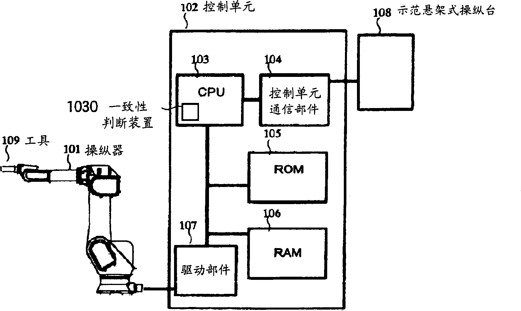
[0037] Now, will refer to Figures 1 to 4 Preferred embodiments for carrying out the present invention are described. figure 1The structure of an industrial robot implementing the present invention is shown. exist figure 1 Among them, 101 is a manipulator, 109 is a tool such as a welding torch or a manual switch unit attached to the industrial robot according to the purpose of use of the industrial robot, 102 is a control unit for controlling the robot as a whole, and 108 is a tool for operating the industrial robot. The exemplary pendant of manipulator and control unit, 103 is CPU, is used for controlling the control unit itself that comprises consistency judging device 1030, thereby judges the consistency of software, 104 is used for and demonstration pendant 108 The communication part of the control unit for communication, 105 is the ROM which is a read-only memory storing the control unit software (not shown) to be interpreted by the CPU for operation, 106 is the RAM w...
Embodiment 2
[0046] will refer to figure 1 , 2 , 3 and 5 describe preferred embodiments for implementing the present invention. In this embodiment, substantially the same elements as in Embodiment 1 will be denoted by the same reference numerals or symbols, and detailed description of the elements will be omitted.
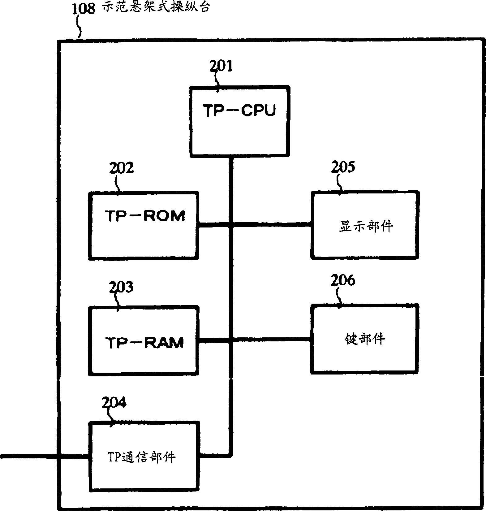
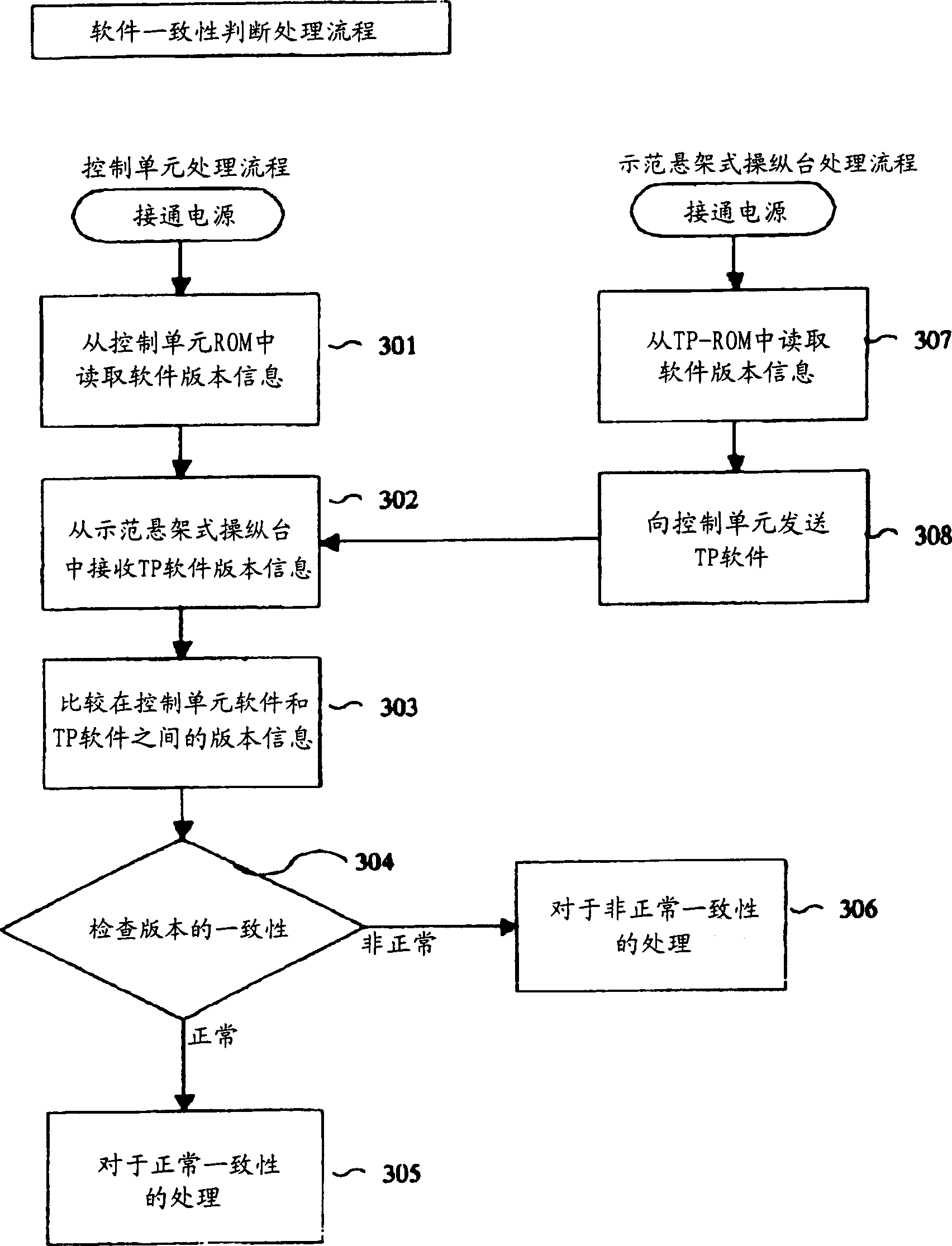
[0047] exist image 3 After checking whether the version consistency is normal or abnormal in the flow of , in the case that the version consistency has been determined to be abnormal, the CPU 103 in the control unit 102 will display the abnormal consistency via the control unit communication part 104 The commands are sent to the demonstration pendant 108. The TP-CPU 201 in the exemplary pendant 108 will receive a command for displaying abnormal conformity via the TP communication section 204 , and will display the abnormal state of the version conformance in the display section 205 . Figure 5 An example is shown in which an abnormal state of version conformance is displa...
Embodiment 3
[0049] will refer to figure 1 , 2 , 6, 7 and 8 describe preferred embodiments for implementing the present invention. In this embodiment, substantially the same elements as in Embodiment 1 will be denoted by the same reference numerals or signs, and detailed description of the elements will be omitted. In this embodiment, the ROM 105 of the control unit 102 and the TP-ROM 202 of the exemplary pendant 108 are writable, and both the control unit software and the TP software are stored as a pair.
[0050] exist Image 6 In step 601 of the process, the version information of the control unit software will be stored in variable A, and the version information of TP software will be stored in variable B. Then, at step 602 of the flow, the integer part of variable A, ie only the master version, will be stored in variable INT_A, and the integer part of variable B will be stored in variable INT_B. Then, at step 603 INT_A is compared with INT_B. Since INT_A and INT_B correspond to ...
PUM
 Abstract
Description
Claims
Application Information