Numerical control machine tool capable of draining water conveniently

A technology of CNC machine tools and machine tools, applied in metal processing machinery parts, maintenance and safety accessories, metal processing equipment, etc., can solve the problems of blockage of drainage pipes, inconvenient recycling of metal chips and cutting fluid, and lack of filtration of chips, etc. To achieve the effect of preventing clogging

Inactive Publication Date: 2021-03-16
王增留
View PDF8 Cites 1 Cited by
  • Summary
  • Abstract
  • Description
  • Claims
  • Application Information

AI Technical Summary

Problems solved by technology

[0006] Aiming at the deficiencies of the prior art, the present invention provides a numerically controlled machine tool that is convenient for drainage, which solves the problem that most of the numerically controlled machine tools directly lead the cutting fluid through the water pipe. Since the cutting fluid contains a large amount of metal debris, these debris are easy to deposit and block. As a result, the drainage pipe is blocked, and the debris in the cutting fluid lacks effective filtration, which is not convenient for the recycling of metal debris and cutting fluid

Method used


Image

  • Numerical control machine tool capable of draining water conveniently
  • Numerical control machine tool capable of draining water conveniently
  • Numerical control machine tool capable of draining water conveniently

Examples


Embodiment 1

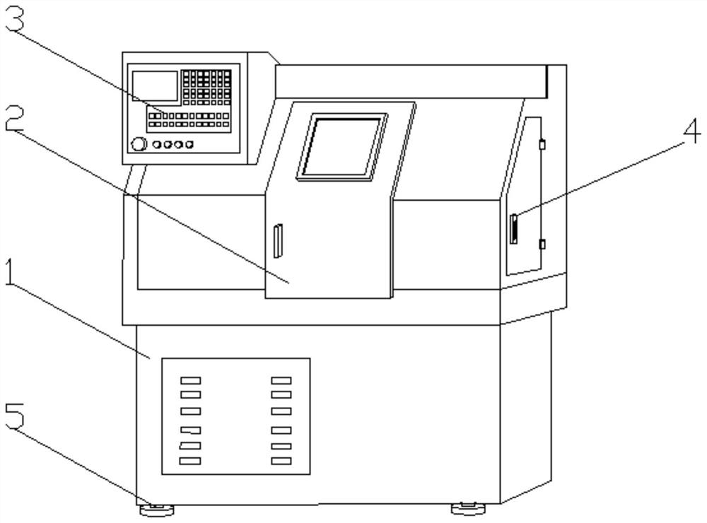
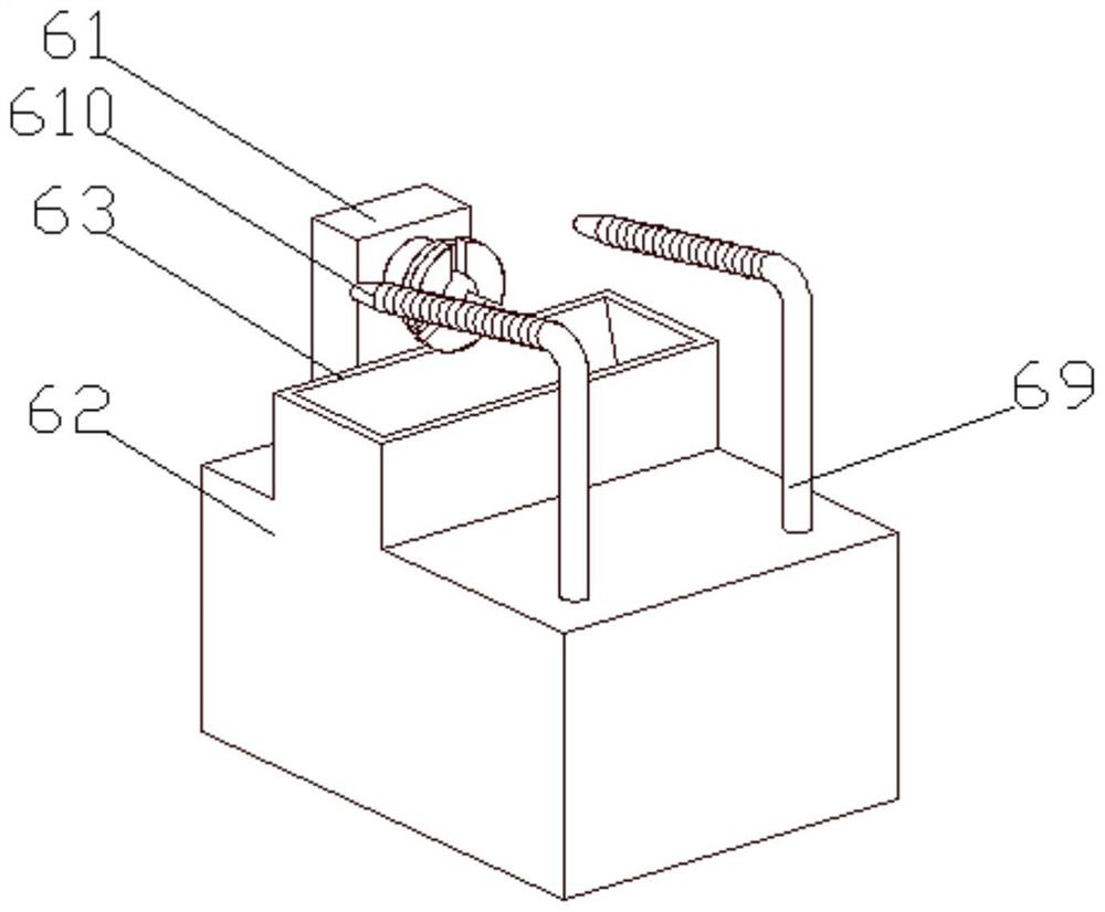
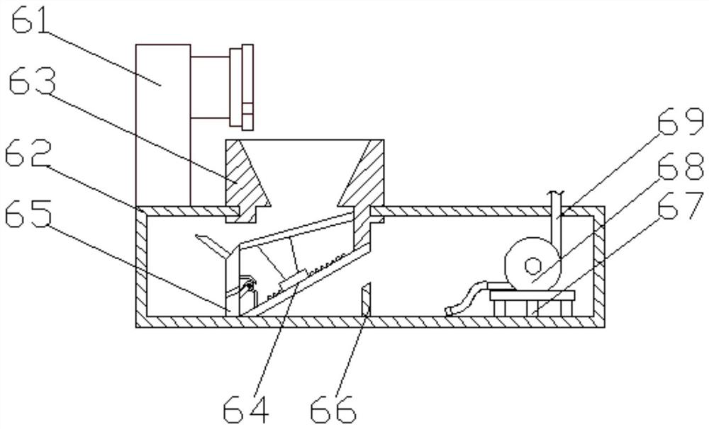
[0038] see Figure 1-3 , the present invention provides a technical solution: a numerically controlled machine tool that is convenient for drainage, including a machine tool shell 1, a machine tool sliding window 2 and a machine tool control panel 3 are arranged on one side of the machine tool shell 1, and one side of the machine tool shell 1 passes through The hinge is rotatably connected with a machine tool protection door panel 4, and the four corners of the bottom of the machine tool housing 1 are fixedly connected with protective pads 5, and a processing mechanism 6 is arranged inside the machine tool housing 1, and the processing mechanism 6 includes a machine tool processing device 61, one end of the machine tool processing device 61 A liquid storage case 62 is fixedly connected, and a liquid discharge bucket 63 is arranged on the top side of the liquid storage case 62 close to the machine tool processing device 61. The bottom of the inner wall of the liquid storage case...

Embodiment 2

[0040] see Figure 1-5 , on the basis of Embodiment 1, the present invention provides a technical solution: a numerically controlled machine tool that facilitates drainage, the first filter mechanism 64 includes a first filter plate a1, and a first through hole a2 is opened on the top of the first filter plate a1 , one side of the first filter plate a1 is provided with a through-hole mechanism a3, the end of the through-hole mechanism a3 away from the first filter plate a1 is provided with a second filter plate a4, and the side of the second filter plate a4 close to the through-hole mechanism a3 is fixed The rack a5 is connected, one side of the second filter plate a4 is provided with a communication port a6, the through hole mechanism a3 includes a through hole base shell a31, one side of the through hole base shell a31 is opened with a through groove a32, the through hole base The side of the inner wall of the housing a31 is fixedly connected with a circulation motor a33, th...

Embodiment 3

[0043] see Figure 1-9 , on the basis of Embodiment 2, the present invention provides a technical solution: a numerically controlled machine tool that facilitates drainage, the second filter mechanism 65 includes a fixed column b1, and a first drain hole b2 is opened on the top of the fixed column b1, and the fixed column b1 One side of b1 is provided with a first drainage groove b3, one side of the first drainage hole b2 is connected with a filter housing b4, and the side of the filter housing b4 away from the first drainage hole b2 is provided with a tapered through hole b5 One side of the filter housing b4 is fixedly connected with the first connecting frame b6, and the end of the first connecting frame b6 away from the filter housing b4 is connected with the first magnet b7 through the rotation of the electric control rolling roller, and the side of the first magnet b7 is provided with The first chip removal shovel b8, the end of the first chip removal shovel b8 away from ...


PUM


Abstract

The invention discloses a numerical control machine tool capable of draining water conveniently. The numerical control machine tool comprises a machine tool machining device, a liquid storage shell isfixedly connected to one end of the machine tool machining device, a liquid draining hopper is arranged on the side, close to the top of the machine tool machining device, of the liquid storage shell, a first filtering mechanism is fixedly connected to the bottom of the inner wall of the liquid storage shell, a second filtering mechanism is fixedly connected to one side of the first filtering mechanism, and a balance plate is fixedly connected to the end, away from the second filtering mechanism, of the first filtering mechanism. A supporting frame is fixedly connected to the bottom of the inner wall, away from the balance plate, of the liquid storage shell, a circulating pump is fixedly connected to the top of the supporting frame, the input end of the circulating pump communicates withthe interior of the liquid storage shell through a pipeline, and the output end of the circulating pump communicates with a spraying pipeline. The invention relates to the technical field of machining. According to the numerical control machine tool capable of draining water conveniently, the situation that scrap iron enters the liquid storage shell along with cutting liquid is reduced, the quality of the cutting liquid is improved, the utilization rate of the cutting liquid is increased, and the working cost is reduced.

Description

technical field [0001] The invention relates to the technical field of mechanical processing, in particular to a numerically controlled machine tool that is convenient for drainage. Background technique [0002] CNC machine tool is an automatic machine tool equipped with a program control system. CNC machine tool solves the problem of complex, precise, small batch and multi-variety parts processing. Cutting fluid is a kind of metal cutting and grinding process. It is an industrial liquid used to cool and lubricate cutting tools and workpieces. The cutting fluid is made of a variety of super functional additives through scientific compounding, and has good cooling and lubricating properties. [0003] For example, Chinese patent CN109108716A discloses a numerically controlled machine tool that facilitates the separation and collection of waste slag, including a fuselage shell. , the bottom end of the fuselage shell is provided with a storage chamber, and a storage board is in...

Claims


Application Information

Patent Timeline
Patent Type & Authority Applications(China)
IPC IPC(8): B23Q11/10
CPCB23Q11/1069B23Q11/10
Inventor 王增留
Owner 王增留
Why Eureka
Try Eureka