Minitype nonradiative dielectric waveguide path guide mode suppressor

一种非辐射、波导线的技术,应用在波导型器件、波导、电路等方向,能够解决需要时间和劳力等问题,达到设计灵活、减少弯曲半径的效果

Inactive Publication Date: 2010-06-23
INTELLIGENT COSMOS RES INST
View PDF4 Cites 1 Cited by
  • Summary
  • Abstract
  • Description
  • Claims
  • Application Information

AI Technical Summary

Problems solved by technology

[0007] The problem with the above-mentioned existing mode suppressor 103 is: when it is to be inserted in the dielectric line 101, it is necessary to Cutting in the longitudinal direction, inserting the mode suppressor 103 in the cut and sticking it, must go through such troublesome steps that require time and labor

Method used


Image

  • Minitype nonradiative dielectric waveguide path guide mode suppressor
  • Minitype nonradiative dielectric waveguide path guide mode suppressor
  • Minitype nonradiative dielectric waveguide path guide mode suppressor

Examples


Embodiment 1

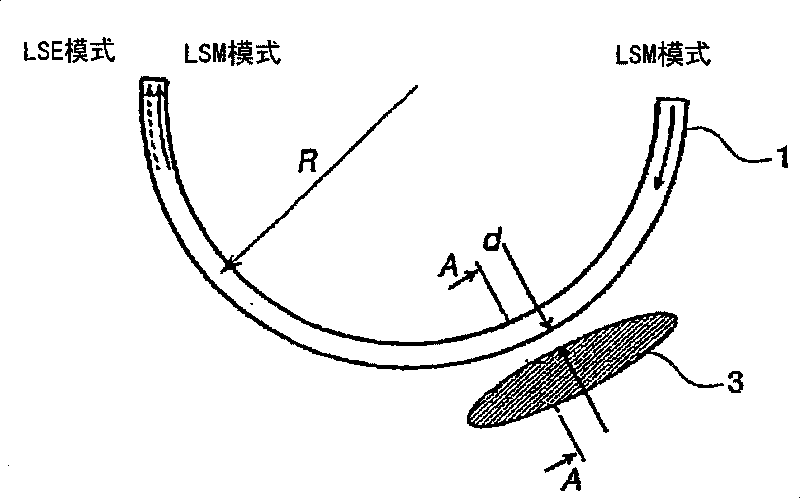
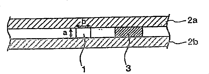
[0055] figure 1 It is a schematic diagram showing the schematic structure of the NRD guided-wave mode suppressor according to Embodiment 1 of the present invention. in addition, figure 2 is along figure 1 Cross-sectional view of line A-A of the NRD guided mode suppressor shown. exist figure 1 and figure 2 Among them, the NRD guided wave suppressor includes a dielectric line 1 interposed in parallel conducting plates 2a, 2b. Dielectric circuit 1 adopts dielectric constant εr=2.04, tan δ=1.5×10 -4 Left and right Teflon (R), and the height a is taken as 2.25mm, and the width b is taken as 2.5mm. If the operating frequency of the electromagnetic wave propagating on the dielectric line 1 is taken as 60 GHz, its wavelength λ is 5 mm, and the height a becomes less than λ / 2, so that the electromagnetic wave of the operating frequency does not propagate on the conductive plate other than the dielectric line 1 Between 2a and 2b. On the other hand, the wavelength λ can be sh...

Embodiment 2

[0063] Next, Embodiment 2 of the present invention will be described. In the above-mentioned embodiment 1, the LSE mode is suppressed under the situation that the dielectric line 1 of the NRD waveguide device is conventionally bent, but in this embodiment 2, the LSE mode in the NRD waveguide device as the function of the 3dB coupler is suppressed. mode is suppressed.

[0064] Figure 9 It is a schematic diagram showing a schematic structure of an NRD mode suppressor suitable for a 3dB coupler applied to Embodiment 2 of the present invention. exist Figure 9 Among them, the 3dB coupler is provided with curved semicircular dielectric lines 21, 22 close to each other, and the electromagnetic wave of the working frequency input from the other port P1 of the dielectric line 21 is between the adjacent dielectric lines 21, 22. 3dB coupling is performed, and the electromagnetic wave of the working frequency is output from another port P4 of the dielectric line 22 . Here, similarly...

Embodiment 3

[0068] Furthermore, Embodiment 3 of the present invention will be described. In Embodiment 3, an NRD guided wave mode suppressor capable of suppressing the LSE mode and completely reproducing the input LSM mode is implemented.

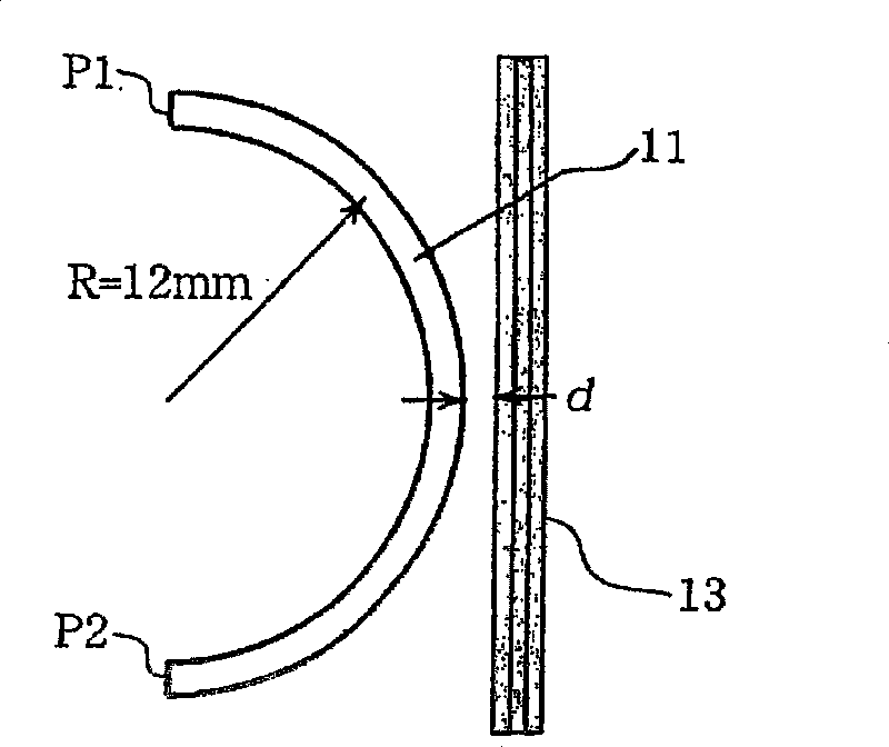
[0069] First, the working principle of Embodiment 3 will be described. imagine as Figure 11 In the shown dielectric line 31 , the electromagnetic wave of the working frequency is input from the port P1 at one end of the dielectric line 31 , propagates in the dielectric line 31 and is output from the port P2 . In addition, the radius of curvature of the medium line 31 is R, the angle between the port P1 and a given position on the medium line 31 is θ, and the distance between the port P1 and a given position on the medium line 31 is z.

[0070] The electromagnetic wave input on the port P1 propagates in the state of mixed LSM mode and LSE mode, and each electromagnetic wave is a 1 (z), a 2 When (z), the amplitude of each electromagnetic wave of LSM...


PUM


Abstract

The invention has simple structure, and can effectively control a spurious mode, namely an LSE mode to realize compact light weight. And a metal body 3 is arranged on the vicinity of a medium circuit 1 of an NRD waveguide component, the NRD waveguide component is clamped in parallel conductive plates, and electromagnetic wave is transited through the medium circuit 1 whose gap is taken smaller than 1 / 2 wave length, thereby inhibiting the LSE mode. The shape of the metal body is designed randomly, which also can adopt shapes such as a disk, an oval plate and a square column and the like. And the phase parameter can be inhibited through maintaining equal gap d by the metal body 3 along the medium circuit 1 and changing the gap d.

Description

technical field [0001] The present invention relates to a kind of NRD guided wave mode suppressor, and this NRD guided wave mode suppressor can be used to realize the NRD waveguide device (Nonradiative Dielectric Waveguide Line: Nonradiative Dielectric Wave Guide ), that is, the electromagnetic field of the LSE mode is controlled and output, especially about an NRD guided wave mode suppressor used in the millimeter wave frequency band. Background technique [0002] In recent years, there is a desire to realize ultra-high-speed, large-capacity wireless communication, and in order to realize such communication, it is useful to use a millimeter-wave frequency band that does not require a license required by the Radio Wave Act. Of particular importance is the development of a broadband circuit element that covers the 59 to 66 GHz frequency band. With this, transmission speeds exceeding, for example, 400 Mbps have been achieved in wireless transmissions such as ultra-high-speed ...

Claims


Application Information

Patent Timeline
Patent Type & Authority Patents(China)
IPC IPC(8): H01P3/16H01P5/18H01P1/16
CPCH01P1/16H01P3/165H01P3/16H01P5/18
Inventor 米山务泽田浩和
Owner INTELLIGENT COSMOS RES INST
Why Eureka
Try Eureka